C1377/43
Diagnostic trouble codes
DESCRIPTION
The brake control power supply assembly (capacitor) provides auxiliary power for brake control when an auxiliary battery (12 V) voltage drops.| DTC No. |
INF Code |
DTC Detecting Condition |
Trouble Area |
| C1377/43 |
101 |
Brake control power supply assembly is deteriorated (indicates a need to replace). |
|
| C1377/43 |
102 |
Self-discharge (current leak) is excessive (internal malfunction). |
|
| C1377/43 |
103 |
Input voltage from the auxiliary battery (12 V) to the brake control power supply is 16.4 V or more for at least 10 sec. |
|
| C1377/43 |
105 |
Circuit inside the power back up unit (charge) is malfunctioning. |
|
| C1377/43 |
106 |
Circuit inside the power back up unit (back up output circuit) is malfunctioning. |
|
| C1377/43 |
108 |
Circuit inside the power back up unit (voltage monitor circuit) is malfunctioning. |
|
| C1377/43 |
109 |
Open circuit between auxiliary battery (12 V) and brake control power supply power input (+BC terminal). |
|
| C1377/43 |
110 |
|
|
WIRING DIAGRAM
Refer to DTCs C1241/41 and C1242/42 (Click here).INSPECTION PROCEDURE
- NOTICE:
- When replacing the skid control ECU, perform initialization of linear solenoid valve and calibration (Click here).
| 1. CHECK FREEZE FRAME DATA |

Check the INF code from the FREEZE FRAME DATA memorized when the DTC (C1337/43) is stored (Click here).
- Result:
Condition
Proceed To
INF codes (109 and 110) are output
A
INF codes (101, 102, 105, 106 and 108) are output
B
INF code (103) is output
C
|
|
||||
|
|
||||


| A | |
 |
| 2. INSPECT FUSE (ABS NO.3 FUSE) |
Remove the ABS No.3 fuse from the engine room R/B No.4.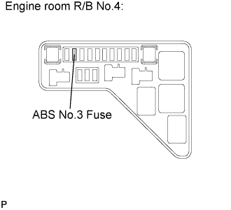

Check the ABS No.3 fuse.
- Resistance:
- Below 1 Ω (Continuity)
|
|
||||
| OK | |
|
| 3. INSPECT BRAKE CONTROL POWER SUPPLY (+BC TERMINAL) |
Measure the voltage according to the value(s) in the table below.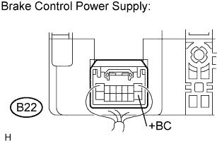
- HINT:
- Measure the voltage from the back side of the connector with the connector connected.
- Voltage:
Tester Connection
Specified Condition
B22-8 (+BC) - Body ground
10 to 14 V
|
|
||||
| OK | |
|
| 4. INSPECT SKID CONTROL ECU (+BI1, +BI2 TERMINAL) |
Measure the voltage according to the value(s) in the table below.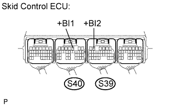
- HINT:
- Measure the voltage from the back side of the connector with the connector connected to the skid control ECU.
- Voltage:
Tester Connection
Specified Condition
S40-3 (+BI1) - Body ground
10 to 14 V
S39-5 (+BI2) - Body ground
10 to 14 V
|
|
||||
| OK | |
|
| 5. INSPECT SKID CONTROL ECU (+BO1, +BO2 TERMINAL) |
Measure the voltage according to the value(s) in the table below.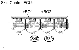
- HINT:
- Measure the voltage from the back side of the connector with the connector connected to the skid control ECU.
- Voltage:
Tester Connection
Specified Condition
S40-5 (+BO1) - Body ground
10 to 14 V
S39-4 (+BO2) - Body ground
10 to 14 V
|
|
||||
| OK | |
|
| 6. INSPECT BRAKE CONTROL POWER SUPPLY (+BCTY, OUT1, OUT2 TERMINAL) |
Turn the ignition switch on.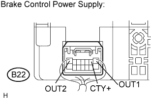
Measure the voltage according to the value(s) in the table below.
- HINT:
- Measure the voltage from the back side of the connector with the connector connected.
- Voltage:
Tester Connection
Condition
Specified Condition
B22-1 (OUT1) - Body ground
Ignition switch ON
9 to 13 V
B22-2 (CTY+) - Body ground
Ignition switch ON
9 to 13 V
B22-7 (OUT2) - Body ground
Ignition switch ON
9 to 13 V
|
|
||||
| NG | ||
 |
||
| ||
| 7. INSPECT BATTERY |
Check the battery voltage.
- Voltage:
- 10 to 14 V
|
|
||||
| OK | |
|
| 8. INSPECT BRAKE CONTROL POWER SUPPLY (+BC TERMINAL) |
Measure the voltage according to the value(s) in the table below.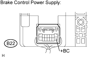
- HINT:
- Measure the voltage from the back side of the connector with the connector connected.
- Voltage:
Tester Connection
Specified Condition
B22-8 (+BC) - Body ground
9 to 13 V
|
|
||||
| OK | ||
|
||
| ||