C1378/44
Diagnostic trouble codes
DESCRIPTION
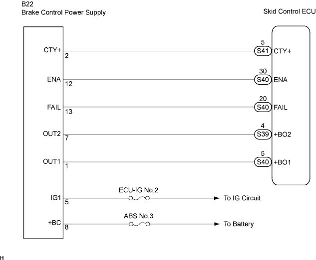
The brake control power supply assembly (capacitor) provides auxiliary power for brake control when an auxiliary battery (12 V) voltage drops.The FAIL and ENA lines are placed between the skid control ECU and the brake control power supply assembly.
Signals indicating that the brake control power supply is in auxiliary mode are sent to the skid control ECU through the FAIL line.
Charge permit prohibition signals are sent to the brake control power supply through the ENA line.
| DTC No. |
INF Code |
DTC Detecting Condition |
Trouble Area |
| C1378/44 |
112 |
|
|
WIRING DIAGRAM

INSPECTION PROCEDURE
- NOTICE:
- When replacing the skid control ECU, perform initialization of linear solenoid valve and calibration (Click here).
| 1. INSPECT BRAKE CONTROL POWER SUPPLY (IG1 TERMINAL) |

Measure the voltage according to the value(s) in the table below.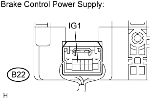
- HINT:
- Measure the voltage from the back side of the connector with the connector connected to the skid control ECU.
- Voltage:
Tester Connection
Condition
Specified Condition
B22-5 (IG1) - Body ground
Ignition switch ON
10 to 14 V
|
|
||||

| OK | |
 |
| 2. CHECK HARNESS AND CONNECTOR (BETWEEN SKID CONTROL ECU AND BRAKE CONTROL POWER SUPPLY) |
Turn the ignition switch off.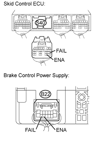
Disconnect the skid control ECU connector and brake control power supply connector.
Measure the resistance according to the value(s) in the table below.
- Resistance:
Tester Connection
Specified Condition
S40-30 (ENA) - B22-12 (ENA)
Below 1 Ω
S40-20 (FAIL) - B22-13 (FAIL)
Below 1 Ω
Measure the resistance according to the value(s) in the table below.
- Resistance:
Tester Connection
Specified Condition
S40-30 (ENA) - Body ground
10 kΩ or higher
S40-20 (FAIL) - Body ground
10 kΩ or higher
|
|
||||
| OK | |
|
| 3. CHECK FREEZE FRAME DATA |
Check the INF code from the FREEZE FRAME DATA memorized when the DTC (C1378/44) is stored (Click here).
- Result:
Condition
Proceed To
INF codes are not output
A
INF code (112) is output
B
|
|
||||
| A | ||
 |
||
| ||