P0500 Vehicle speed signal from vehicle speed sensor is cut for 0.14 sec. or more while cruise control is in...
Diagnostic trouble codes
DESCRIPTION
The speed sensor detects the wheel speed and sends the appropriate signals to the skid control ECU. The skid control ECU converts these wheel speed signals into a 4 pulse signal and outputs it to the hybrid vehicle control ECU via the combination meter. The hybrid vehicle control ECU determines the vehicle speed based on the frequency of these pulse signals.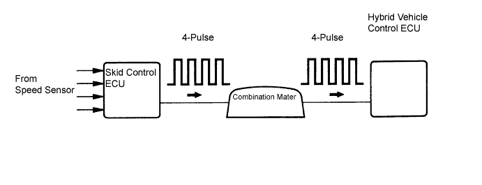

| DTC No. |
DTC Detection Condition |
Trouble Area |
| P0500 |
Vehicle speed signal from vehicle speed sensor is cut for 0.14 sec. or more while cruise control is in operation |
|
WIRING DIAGRAM
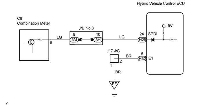
INSPECTION PROCEDURE
| 1. CHECK OPERATION OF SPEEDOMETER |

Drive the vehicle and check if operation of the speedometer in the combination meter is normal.
- OK:
- Actual vehicle speed and the speed indicated on the speedometer are the same.
- HINT:
- The vehicle speed sensor is operating normally if the speedometer display is normal.
|
|
||||

| OK | |
 |
| 2. READ VALUE OF INTELLIGENT TESTER |
Connect the intelligent tester to the DLC3.
Turn the ignition switch on.
Select the item "VEHICLE SPD" in the DATA LIST and check that the speed displayed on the tester screen is the same as the one indicated on the combination meter.
| Item |
Measurement Item/Display (Range) |
Normal Condition |
Diagnostic Note |
| VEHICLE SPD |
Cruise control vehicle speed/min.: 0 km/h (0 mph) max.: 255 km/h (158 mph) |
Actual vehicle speed |
- |
- OK:
- The speed displayed on the tester screen is almost the same as the speed the one indicated on the combination meter.
|
|
||||

| OK | ||
 |
||
| ||
| 3. INSPECT HYBRID VEHICLE CONTROL ECU (SPD VOLTAGE) |
Shift the lever to the neutral position.
Jack up the vehicle.
Turn the ignition switch on.
Measure the voltage between the specified terminals of the H29 and H32 hybrid vehicle control ECU connectors as the wheel is turned slowly.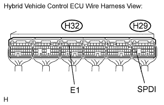
- Standard voltage:
Tester Connection
Specified Condition
SPDI (H29-24) - E1 (H32-5)
Generated intermittently
Refer to HINT below.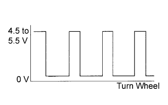
- HINT:
- The output voltage should fluctuate up and down similarly to the diagram on the left when the wheel is turned slowly.
|
|
||||
| OK | ||
|
||
| ||
| 4. CHECK HARNESS AND CONNECTOR |
Disconnect the H29 connector of the hybrid vehicle control ECU.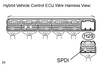
Disconnect the C8 connector of the combination meter.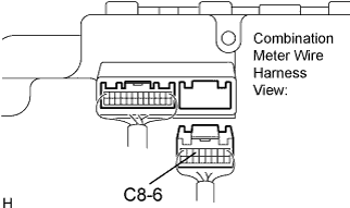
Measure the resistance according to the value(s) in the table below.
- Standard resistance:
Tester Connection
Condition
Specified Value
H29-24 (SPDI) - C8-6
Always
Below 1 Ω
H29-24 (SPDI) - Body ground
Always
10 kΩ or higher
|
|
||||
| OK | ||
|
||
| ||