P0571 When voltage of STP terminal and that of ST1- terminal on the hybrid vehicle control ECU are less than 1 V...
Diagnostic trouble codes
DESCRIPTION
When the brake pedal is depressed, the stop light switch sends a signal to the hybrid vehicle control ECU. When the hybrid vehicle control ECU receives this signal, it cancels the cruise control. Fail-safe function operates to enable normal driving even if there is a malfunction in the stop light signal circuit. The cancellation condition occurs when voltage is applied to terminal STP. When the brake is applied, voltage is normally applied to terminal STP of the hybrid vehicle control ECU through the STOP SW fuse and the stop light switch, and the hybrid vehicle control ECU turns the cruise control off.| DTC No. |
DTC Detection Condition |
Trouble Area |
| P0571 |
When voltage of STP terminal and that of ST1- terminal on the hybrid vehicle control ECU are less than 1 V for 0.5 sec. or more |
|
WIRING DIAGRAM
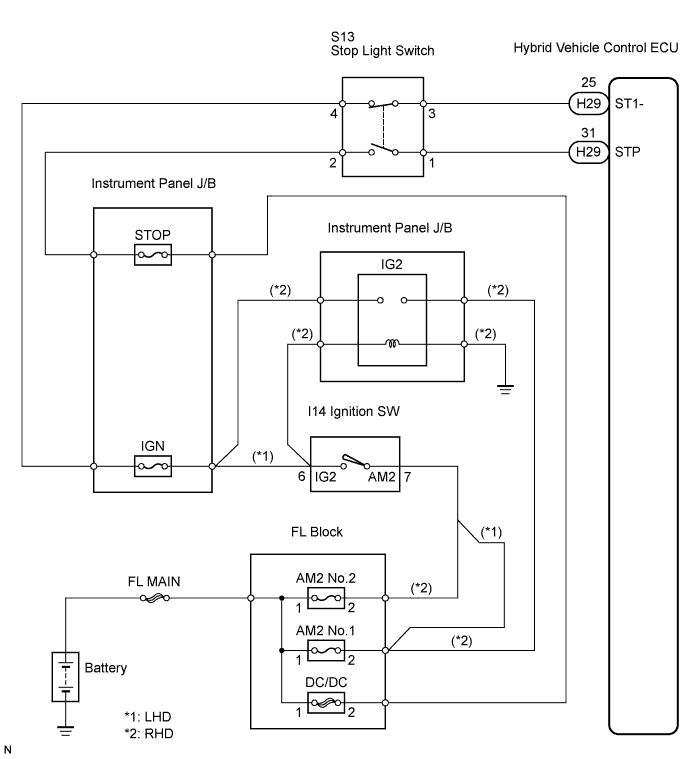

INSPECTION PROCEDURE
| 1. READ VALUE OF INTELLIGENT TESTER |

Connect the intelligent tester to the DLC3.
Turn the ignition switch on, and turn the intelligent tester main switch on.
Check the DATA LIST for proper functioning of the stop light switch.
Hybrid Vehicle Control ECU (Cruise control): Item
Measurement Item / Display (Range)
Normal Condition
Diagnostic Note
STP LIGHT SW M
Stop light switch signal (Main CPU) / ON or OFF
ON: Brake pedal depressed
OFF: Brake pedal released
-
- OK:
- When brake pedal operation is performed the results will be same as above.
|
|
||||

| NG | |
 |
| 2. INSPECT STOP LIGHT SWITCH |
Disconnect the stop light switch connector.
Measure the resistance according to the value(s) in the table below.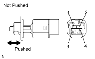
- Standard resistance:
Tester Connection
Switch Condition
Specified Condition
1 - 2
Switch pin not pushed
Below 1 Ω
3 - 4
Switch pin not pushed
10 kΩ or higher
1 - 2
Switch pin pushed
10 kΩ or higher
3 - 4
Switch pin pushed
Below 1 Ω
|
|
||||
| OK | |
|
| 3. CHECK WIRE HARNESS (STOP LIGHT SWITCH - BATTERY) |
Measure the voltage according to the value(s) in the table below.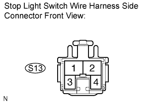
- Standard voltage:
Tester Connection
Condition
Specified Condition
S13-2 - Body ground
Always
10 to 14 V
S13-3 - Body ground
Engine switch on (IG)
10 to 14 V
|
|
||||
| OK | |
|
| 4. CHECK HYBRID VEHICLE CONTROL ECU |
Reconnect the stop light switch connector.
Disconnect the H29 connector from the hybrid vehicle control ECU.
Turn the ignition switch on.
Measure the voltage according to the value(s) in the table below.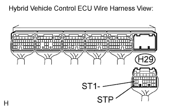
- Standard voltage:
Tester Connection
Brake Pedal Condition
Condition
H29-31 (STP) - Body ground
Depressed
10 to 14 V
H29-31 (STP) - Body ground
Released
Below 1 V
H29-25 (ST1-) - Body ground
Depressed
Below 1 V
H29-25 (ST1-) - Body ground
Released
10 to 14 V
|
|
||||
| OK | ||
 |
||
| ||