TERMINALS OF ECU
System information
| CHECK MULTIPLEX NETWORK MASTER SWITCH ASSEMBLY |
Disconnect the P19 switch connector.
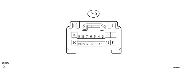

Measure the voltage and resistance according to the value(s) in the table below.
- Standard voltage and resistance:
Symbols
(Terminal No.)
Wiring Color
Terminal Description
Condition
Specified Condition
CPUB (P19-9) - Body ground
L-B - Body ground
+B (CPUB) power supply
Constant
10 to 14 V
BDR (P19-10) - Body ground
G - Body ground
+B (BDR) power supply
Constant
10 to 14 V
SIG (P19-20) - Body ground
BR - Body ground
+B (SIG) power supply
Ignition switch
OFF → ON
Below 1 V → 10 to 14 V
GND (P19-2) - Body ground
W-B - Body ground
Ground
Constant
Below 1 Ω
KL (P19-4) - Body ground
BR - Body ground
Driver door key linked door lock input
Driver door key cylinder
OFF → LOCK
10 kΩ or higher → Below 1 Ω
KUL (P19-14) - Body ground
GR - Body ground
Driver door key linked door unlock input
Driver door key cylinder
OFF → UNLOCK
10 kΩ or higher → Below 1 Ω
LSW (P19-16) - Body ground
P - Body ground
Driver door lock position switch input
Driver door
UNLOCK → LOCK
10 kΩ or higher → Below 1 Ω
- HINT:
- If the result is not as specified, there may be a malfunction on the wire harness side.
Reconnect the switch connector and measure the voltage according to the value(s) in the table below.
- Standard voltage:
Symbols
(Terminal No.)
Wiring Color
Terminal Description
Condition
Specified Condition
KL (P19-4) - Body ground
BR - Body ground
Driver door key linked door lock input
Driver door key cylinder
OFF → LOCK
10 to 14 V → Below 1 V
KUL (P19-14) - Body ground
GR - Body ground
Driver door key linked door unlock input
Driver door key cylinder
OFF → UNLOCK
10 to 14 V → Below 1 V
LSW (P19-16) - Body ground
P - Body ground
Driver door lock position switch input
Driver door
UNLOCK → LOCK
Below 1 V →
10 to 14 V (or pulse generation)
- HINT:
- Use an oscilloscope to check the output voltages of terminal LSW.
- If the result is not as specified, the switch (door ECU) may have a malfunction.
- Use an oscilloscope to check the output voltages of terminal LSW.
| CHECK INSTRUMENT PANEL J/B ASSEMBLY (BODY ECU) |
Disconnect the 1A, 1D, 1F, 1J, 1M, 1O, B5, B6 and B7 connectors.
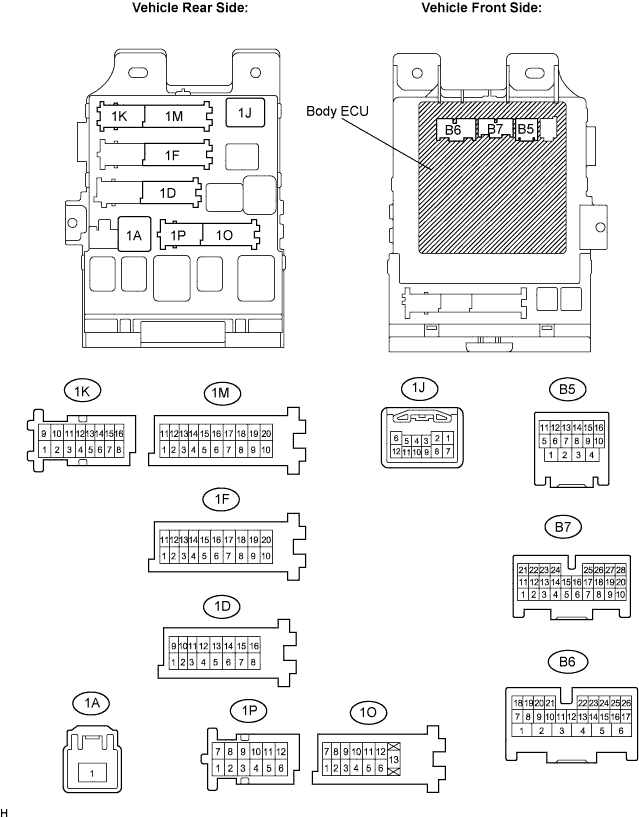
Measure the voltage and resistance according to the value(s) in the table below.
- Standard voltage and resistance:
Symbols
(Terminal No.)
Wiring Color
Terminal Description
Condition
Specified Condition
BECU (1D-10) - Body ground
W - Body ground
+B (BECU) power supply
Constant
10 to 14 V
ALTB (1D-16) - Body ground
W*1, R-Y*2 - Body ground
+B (power system, generator system) power supply
Constant
10 to 14 V
BATB*3 (1K-9) - Body ground
R - Body ground
+B (power system, battery system)power supply
Constant
10 to 14 V
KSW (B6-21) - Body ground
B - Body ground
Key unlock warning switch input
No key in ignition key cylinder →
Key inserted
10 kΩ or higher →
Below 1 Ω
GND1 (1F-10) - Body ground
W-B - Body ground
Ground
Constant
Below 1 Ω
GND2 (1M-9) - Body ground
W-B - Body ground
Ground
Constant
Below 1 Ω
L1 (1J-3)*1, (1K-15)*2 - Body ground
V - Body ground
Passenger door control switch LOCK input
Passenger door control switch
OFF → LOCK
10 kΩ or higher →
Below 1 Ω
UL1 (1J-4)*1, (1K-12)*2 - Body ground
BR - Body ground
Passenger door control switch UNLOCK input
Passenger door control switch
OFF → UNLOCK
10 kΩ or higher →
Below 1 Ω
DCTY (B5-14) - Body ground
L - Body ground
Driver door courtesy switch input
Driver door
CLOSED → OPEN
10 kΩ or higher →
Below 1 Ω
PCTY (B7-23) - Body ground
L - Body ground
Passenger door courtesy switch input
Passenger door
CLOSED → OPEN
10 kΩ or higher →
Below 1 Ω
LCTY (1O-7) - Body ground
B - Body ground
Rear left door courtesy switch input
Rear left door
CLOSED → OPEN
10 kΩ or higher →
Below 1 Ω
RCTY (B5-16) - Body ground
GR - Body ground
Rear right door courtesy switch input
Rear right door
CLOSED → OPEN
10 kΩ or higher →
Below 1 Ω
BCTY (B7-25) - Body ground
P - Body ground
Back door courtesy switch input
Back door
CLOSED → OPEN
10 kΩ or higher →
Below 1 Ω
- HINT:
- *1: LHD Models
- *2: RHD Models
- *3: w/ Double Locking System
- If the result is not as specified, there may be a malfunction on the wire harness side.
- *1: LHD Models
Reconnect the J/B and ECU connectors and measure the voltage according to the value(s) in the table below.
- Standard voltage:
Symbols
(Terminal No.)
Wiring Color
Terminal Description
Condition
Specified Condition
IG (1F-11) - Body ground
Y - Body ground
Ignition power supply
Ignition switch
OFF → ON
10 to 14 V → Below 1 V
ACT+ (1K-2) - Body ground
L - Body ground
Door lock motor LOCK drive output (Front left door)
Door control switch (Master switch or passenger side switch) or driver side door key cylinder
OFF →
LOCK →
OFF
Below 1 V →
10 to 14 V →
Below 1 V
ACT+ (1J-1) - Body ground
L - Body ground
Door lock motor LOCK drive output (Front right door)
Door control switch (Master switch or passenger side switch) or driver side door key cylinder
OFF →
LOCK →
OFF
Below 1 V →
10 to 14 V →
Below 1 V
ACT+ (1P-11) - Body ground
R-Y - Body ground
Door lock motor LOCK drive output (Rear left door)
Door control switch (Master switch or passenger side switch) or driver side door key cylinder
OFF →
LOCK →
OFF
Below 1 V →
10 to 14 V →
Below 1 V
ACT+ (1F-5) - Body ground
L - Body ground
Door lock motor LOCK drive output (Rear right door)
Door control switch (Master switch or passenger side switch) or driver side door key cylinder
OFF →
LOCK →
OFF
Below 1 V →
10 to 14 V →
Below 1 V
ACT- (1F-18) - Body ground
R - Body ground
Door lock motor UNLOCK drive output (Front left and rear right door)
Door control switch (Master switch or passenger side switch) or driver side door key cylinder
OFF →
UNLOCK →
OFF
Below 1 V →
10 to 14 V →
Below 1 V
ACT- (1J-2) - Body ground
R - Body ground
Door lock motor UNLOCK drive output (Front right door)
Door control switch (Master switch or passenger side switch) or driver side door key cylinder
OFF →
UNLOCK →
OFF
Below 1 V →
10 to 14 V →
Below 1 V
ACT- (1P-6) - Body ground
P - Body ground
Door lock motor UNLOCK drive output (Rear left door)
Door control switch (Master switch or passenger side switch) or driver side door key cylinder
OFF →
UNLOCK →
OFF
Below 1 V →
10 to 14 V →
Below 1 V
LSWP (B7-27) - Body ground
Y - Body ground
Passenger door lock position switch input
Passenger door
UNLOCK →
LOCK
Below 1 V →
10 to 14 V (or pulse generation)
LSWL (1P-5) - Body ground
GR - Body ground
Rear left door lock position switch input
Rear left door
UNLOCK →
LOCK
Below 1 V →
10 to 14 V (or pulse generation)
LSWR (B7-5) - Body ground
B - Body ground
Rear right door lock position switch input
Rear right door
UNLOCK →
LOCK
Below 1 V →
10 to 14 V (or pulse generation)
- HINT:
- Use an oscilloscope to check the output voltages of terminals LSWP, LSWL and LSWR.
- If the result is not as specified, the J/B (body ECU) may have a malfunction.
- Use an oscilloscope to check the output voltages of terminals LSWP, LSWL and LSWR.
| CHECK POWER BACK DOOR ECU (w/ Power back door system) |
Disconnect the P10 and P11 ECU connectors.
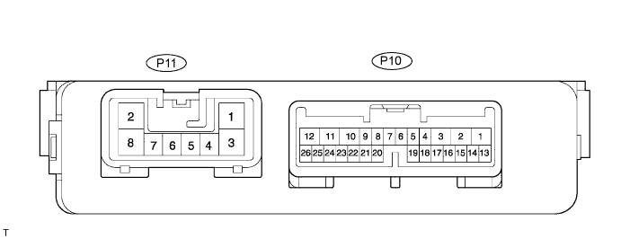
Measure the voltage and resistance according to the value(s) in the table below.
- Standard voltage and resistance:
Symbols
(Terminal No.)
Wiring Color
Terminal Description
Condition
Specified Condition
ECUB (P10-10) - Body ground
BR - Body ground
ECU (ECUB) power supply
Constant
10 to 14 V
B (P11-2) - Body ground
Y - Body ground
+B (ECUB) power supply
Constant
10 to 14 V
GND (P11-8) - Body ground
W-B - Body ground
Ground
Constant
Below 1 Ω
IG (P10-9) - Body ground
GR - Body ground
Ignition switch input
Ignition switch OFF → ON
Below 1 V → 10 to 14 V
CTYE (P10-7) - Body ground
P - Body ground
Back door courtesy switch input
Back door
CLOSED → OPEN
10 kΩ or higher → Below 1 Ω
CTYO (P10-19) - Body ground
BR - Body ground
Back door courtesy switch output
Back door
CLOSED → OPEN
10 kΩ or higher → Below 1 Ω
- HINT:
- If the result is not as specified, there may be a malfunction on the wire harness side.
Reconnect the ECU connectors and measure the voltage according to the value(s) in the table below.
- Standard voltage:
Symbols
(Terminal No.)
Wiring Color
Terminal Description
Condition
Specified Condition
POS (P10-21) - Body ground
LG - Body ground
Back door lock position switch input
Back door OPEN →
Closer in operation →
CLOSED
Below 1 V →
10 to 14 V →
Below 1 V →
FUL (P10-18) - Body ground
V - Body ground
Back door lock full-latch switch input
Back door
CLOSED → OPEN
10 to 14 V → Below 1 V
HAF (P10-8) - Body ground
R - Body ground
Back door lock half-latch switch input
Back door OPEN →
Closer in operation →
CLOSED
Below 1 V →
10 to 14 V →
Below 1 V →
DC+ (P10-12) - Body ground
G - Body ground
Back door lock closer motor drive output (Close)
Back door OPEN →
Not completely closed →
Motor in normal rotation →
Motor in reverse rotation →
Operation completed (Back door CLOSED)
Below 1 V →
Below 1 V →
10 to 14 V →
Below 1 V →
Below 1 V →
DC- (P10-11) - Body ground
B - Body ground
Back door lock closer motor drive output (Release)
Back door OPEN →
Not completely closed →
Motor in normal rotation →
Motor in reverse rotation →
Operation completed (Back door CLOSED)
Below 1 V →
Below 1 V →
Below 1 V →
10 to 14 V →
Below 1 V →
- HINT:
- If the result is not as specified, the ECU may have a malfunction.
| w/ DOUBLE LOCKING SYSTEM |
Disconnect the D2 switch connector.

Measure the voltage and resistance according to the value(s) in the table below.
- Standard voltage and resistance:
Symbols
(Terminal No.)
Wiring Color
Terminal Description
Condition
Specified Condition
+B (D2-1) - Body ground
R - Body ground
+B power suspply
Constant
10 to 14 V
CPUB (D2-7) - Body ground
SB - Body ground
+B (CPUB) power supply
Constant
10 to 14 V
GND (D2-14) - Body ground
W-B - Body ground
Ground
Constant
Below 1 Ω
MPX1 (D2-9) - Body ground
LG - Body ground
BEAN signal input/output
Constant
10 kΩ or higher
- HINT:
- If the result is not as specified, there may be a malfunction on the wire harness side.
Reconnect the D2 relay connector.
Measure the voltage according to the value(s) in the table below.
- Standard voltage:
Symbols
(Terminal No.)
Wiring Color
Terminal Description
Condition
Specified Condition
DLPD (D2-5) - Body ground
GR*1 or P*2- Body ground
Front RH double lock position switch input
Double lock UNSET → SET
5 V or higher → Below 1 V
DLPP (D2-6) - Body ground
P*1 or GR*2- Body ground
Front LH double lock position switch input
Double lock UNSET → SET
5 V or higher → Below 1 V
DLPR (D2-11) - Body ground
W - Body ground
Rear RH double lock position switch input
Double lock UNSET → SET
5 V or higher → Below 1 V
DLPL (D2-12) - Body ground
V - Body ground
Rear LH double lock position switch input
Double lock UNSET → SET
5 V or higher → Below 1 V
ACTS (D2-3) - Body ground
B - Body ground
All door double lock motor set on output
Double lock UNSET → SET
Below 1 V → 10 to 14 V
ACTR (D2-4) - Body ground
L - Body ground
All door double lock motor set off output
Double lock SET → UNSET
Below 1 V → 10 to 14 V
- HINT:
- *1: LHD models
- *2: RHD models
- If the result is not as specified, the relay may have a malfunction.
- *1: LHD models