DIAGNOSIS SYSTEM
Troubleshooting
| DESCRIPTION |
Power door lock control system data can be read through the Data Link Connector 3 (DLC3) of the vehicle. When the system seems to be malfunctioning, use the intelligent tester to check for malfunctions and perform repairs.
| CHECK DLC3 |
The vehicle's ECU uses ISO 9141-2 (Euro-OBD)/ISO 14230 (M-OBD) for communication. The terminal arrangement of the DLC3 complies with ISO 15031-03 and matches the ISO 9141-2/ISO 14230 format.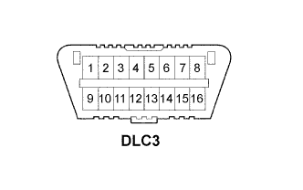

Symbols (Terminal No.)
Terminal Description
Condition
Specified Condition
SIL (7) - SG (5)
Bus "+" line
During transmission
Pulse generation
CG (4) - Body ground
Chassis ground
Always
Below 1 Ω
SG (5) - Body ground
Signal ground
Always
Below 1 Ω
BAT (16) - Body ground
Battery positive
Always
11 to 14 V
CANH (6) - CANL (14)
HIGH-level CAN bus line
Ignition switch OFF
54 to 67 Ω
CANH (6) - Battery positive
HIGH-level CAN bus line
Ignition switch OFF
1 MΩ or higher
CANH (6) - CG (4)
HIGH-level CAN bus line
Ignition switch OFF
3 kΩ or higher
CANL (14) - Battery positive
LOW-level CAN bus line
Ignition switch OFF
1 MΩ or higher
CANL (14) - CG (4)
LOW-level CAN bus line
Ignition switch OFF
3 kΩ or higher
- HINT:
- If the display shows a communication error message after connecting the intelligent tester to the DLC3 and turning the ignition switch to the ON position, there is a problem with either the vehicle or the tester.
- If communication is normal when the tester is connected to another vehicle, inspect the DLC3 on the original vehicle.
- If communication is still impossible when the tester is connected to another vehicle, the problem is probably in the tester itself. Consult the Service Department listed in the tester's instruction manual.
- If communication is normal when the tester is connected to another vehicle, inspect the DLC3 on the original vehicle.