INSTALLATION
Removal / installation
- NOTICE:
- When installing, coat the parts indicated by arrows with molybdenum disulfide lithium base grease (Click here).
| 1. INSTALL STEERING SHAFT UNIVERSAL JOINT ASSEMBLY |

Align the matchmarks on the steering shaft universal joint assembly and the steering column assembly.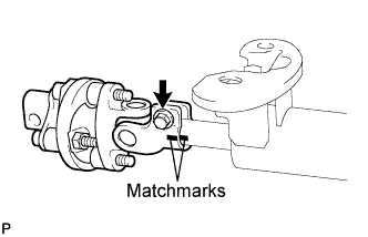

Install the bolt.
- Torque:
- 35 N*m{ 360 kgf*cm , 26 ft.*lbf }
| 2. INSTALL STEERING COLUMN HOLE COVER SUB-ASSEMBLY NO.2 |
Apply molybdenum disulfide lithium base grease to the lip of the steering column hole cover sub-assembly No.2.
Install the steering column hole cover sub-assembly No.2 to the steering intermediate shaft sub-assembly.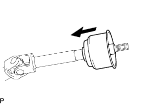
| 3. TEMPORARILY TIGHTEN STEERING INTERMEDIATE SHAFT SUB-ASSEMBLY |
Align the matchmarks on the steering intermediate shaft sub-assembly and the steering shaft universal joint assembly.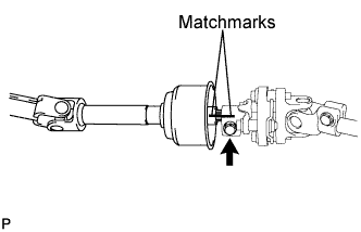
Temporarily install the bolt.
- HINT:
- Do not tighten the bolt.
| 4. INSTALL STEERING COLUMN ASSEMBLY |
Install the steering column assembly with the 2 bolts and 2 nuts.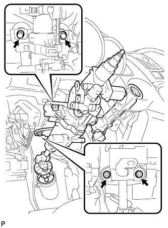
- Torque:
- 26 N*m{ 265 kgf*cm , 19 ft.*lbf }
Connect the connectors to the steering column assembly.
Install the wire harness clamps to the steering column assembly.
| 5. INSTALL INSTRUMENT PANEL FINISH PLATE |
| 6. CONNECT STEERING INTERMEDIATE SHAFT SUB-ASSEMBLY |
Align matchmarks on the steering intermediate shaft sub-assembly and the power steering link assembly.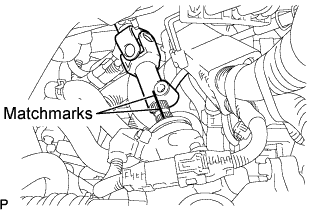
Install the bolt.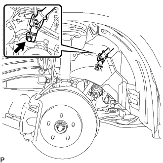
- Torque:
- 35 N*m{ 360 kgf*cm , 26 ft.*lbf }
Tighten the bolt (B).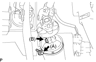
- Torque:
- 35 N*m{ 360 kgf*cm , 26 ft.*lbf }
Install the clamp to the steering column hole shield and tighten the bolt (A).
| 7. INSTALL AIR DUCT NO.1 |
Engage the 3 claws to install the air duct No.1.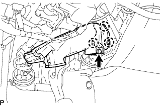
Install the bolt.
| 8. PLACE FRONT WHEELS FACING STRAIGHT AHEAD |
| 9. INSTALL TURN SIGNAL SWITCH ASSEMBLY WITH SPIRAL CABLE SUB-ASSEMBLY |
Install the turn signal switch assembly with spiral cable sub-assembly to the steering column assembly with the clamp.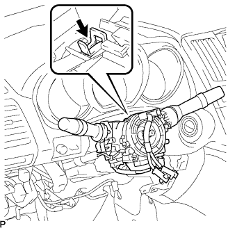
| 10. INSTALL TILT AND TELESCOPIC SWITCH |
Engage the claw to install the tilt and telescopic switch.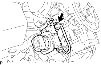
Connect the connector.
| 11. INSTALL STEERING COLUMN COVER |
Engage the claw to install the steering column cover upper.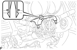
Engage the 2 claws to install the steering column cover lower.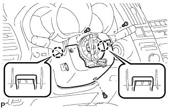
- NOTICE:
- Do not damage the tilt and telescopic switch.
Install the 3 screws.
| 12. ADJUST SPIRAL CABLE SUB-ASSEMBLY |
Check that the ignition switch is off.
Check that the battery negative (-) terminal is disconnected.
- CAUTION:
- After removing the terminal, wait for at least 90 seconds before starting the operation.
Rotate the spiral cable counterclockwise slowly by hand until it feels firm.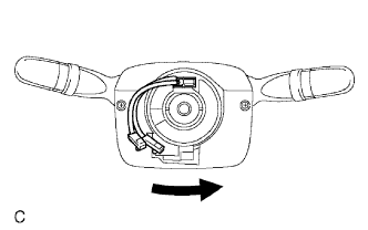
- NOTICE:
- Do not turn the spiral cable by the airbag wire harness.
Rotate the spiral cable clockwise approximately 2.5 turns to align the marks.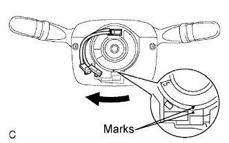
- NOTICE:
- Do not turn the spiral cable by the airbag wire harness.
- HINT:
- The spiral cable will rotate approximately 2.5 turns to both the left and right from the center.
| 13. INSTALL STEERING WHEEL ASSEMBLY |
Align the matchmarks on the steering wheel assembly and steering main shaft assembly.
Install the steering wheel assembly set nut.
- Torque:
- 50 N*m{ 510 kgf*cm , 37 ft.*lbf }
| 14. INSPECT STEERING WHEEL CENTER POINT |
| 15. INSTALL STEERING PAD ASSEMBLY |
Support the steering pad with one hand as shown in the illustration.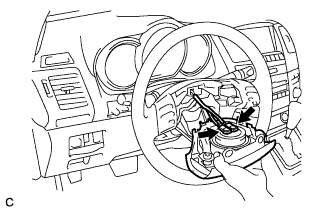
Connect the 2 connectors to the steering pad.
- NOTICE:
- When handling the airbag connector, take care not to damage the airbag wire harness.
Connect the horn connector.
Confirm that the circumference groove of the "torx" screw fits in the screw case, and place the steering pad onto the steering wheel assembly.
Using a "torx" socket wrench (T30), tighten the 2 "torx" screws.
- Torque:
- 8.8 N*m{ 90 kgf*cm , 78 in.*lbf }
| 16. INSTALL STEERING WHEEL COVER LOWER NO.3 |
Install the steering wheel No.3 cover lower.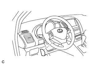
| 17. INSTALL STEERING WHEEL COVER LOWER NO.2 |
Install the steering wheel No.2 cover lower.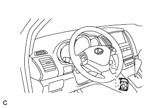
| 18. INSTALL INSTRUMENT PANEL AIRBAG ASSEMBLY LOWER NO.1 |
Install the driver side knee airbag assembly with the 4 bolts.
- Torque:
- 7.6 N*m{ 78 kgf*cm , 68 in.*lbf }
Connect the connector to the driver side knee airbag assembly.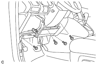
- NOTICE:
- When handling the airbag connector, take care not to damage the airbag wire harness.
| 19. INSTALL INSTRUMENT PANEL FINISH PANEL SUB-ASSEMBLY LOWER |
Connect the connectors.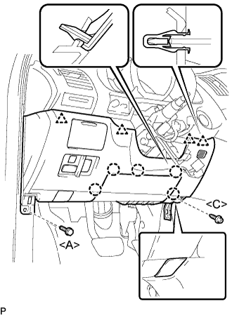
Engage the 5 claws and the 4 clips.
Connect the hood lock control cable assembly.
Install the bolt <A>, the screw <C>, and the instrument panel finish panel sub-assembly lower.
| 20. INSTALL COWL SIDE TRIM SUB-ASSEMBLY LH |
Install the 2 clips and the cowl side trim sub-assembly LH.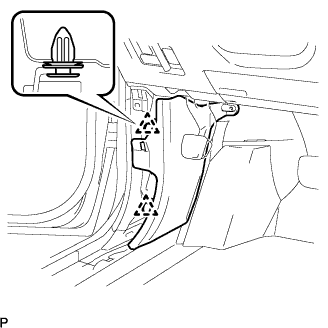
| 21. INSTALL FRONT DOOR SCUFF PLATE LH |
Connect the connector. (w/ illumination scuff plate)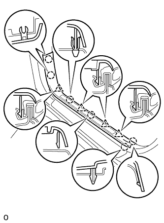
Engage the 6 claws and 4 clips, and install the front door scuff plate.
| 22. INSTALL FRONT WHEEL LH |
- Torque:
- 103 N*m{ 1,050 kgf*cm , 76 ft.*lbf }
| 23. CONNECT CABLE TO NEGATIVE BATTERY TERMINAL |
| 24. CHECK FOR DTCs (POWER TILT AND POWER TELESCOPIC STEERING COLUMN ) |
| 25. INSPECT SRS WARNING LIGHT |
| 26. PERFORM INITIALIZATION |
Some systems need initialization when disconnecting the cable from the negative battery terminal (Click here).