REASSEMBLY
Removal / installation
| 1. INSTALL MULTIPLEX TILT AND TELESCOPIC ECU |

Using a socket wrench (+), install the multiplex tilt and telescopic ECU with the 2 screws.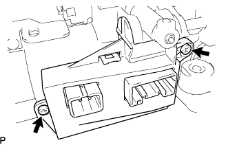

- Torque:
- 1.5 N*m{ 15 kgf*cm , 13 in.*lbf }
Connect the connectors to the multiplex tilt and telescopic ECU.
- NOTICE:
- The connectors on both ends of the wire harness between the telescopic motor and ECU are the same shape.
- When installing them, connect the connectors of the same color.
- The connectors on both ends of the wire harness between the telescopic motor and ECU are the same shape.
| 2. INSTALL IGNITION OR STARTER SWITCH ASSEMBLY |
Install the ignition or starter switch assembly to the steering column upper with switch bracket assembly with the 2 screws.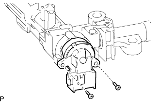
| 3. INSTALL KEY INTER LOCK SOLENOID |
Instal the key inter lock solenoid to the steering column upper with switch bracket assembly with the 2 screws.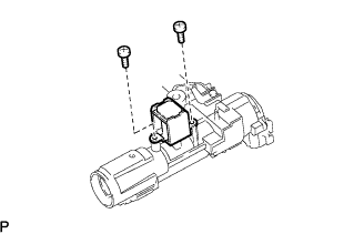
| 4. INSTALL UN-LOCK WARNING SWITCH ASSEMBLY |
Install the un-lock warning switch assembly to the steering column upper with switch bracket assembly.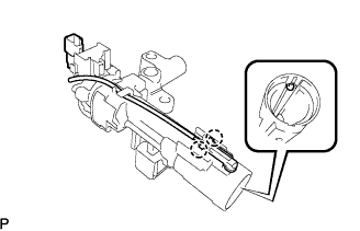
Connect terminals 3 and 4 of the un-lock warning switch assembly connector.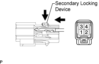
Engage the secondary locking device.
Connect the un-lock warning switch assembly connector to the ignition or starter switch assembly.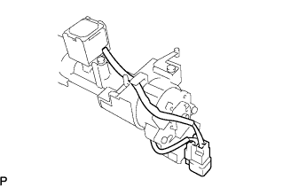
| 5. INSTALL IGNITION SWITCH LOCK CYLINDER ASSEMBLY |
Make sure the ignition switch lock cylinder assembly is in the ACC position.
Install the ignition switch lock cylinder assembly.
Make sure that the ignition switch lock cylinder assembly is securely installed.
| 6. INSPECT STEERING LOCK OPERATION |
Check that the steering lock mechanism is activated when the key is removed.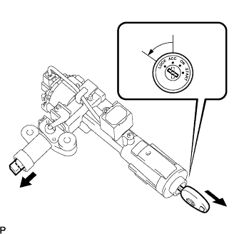
Check that the steering lock mechanism is deactivated when the key is inserted and turned to the ACC position.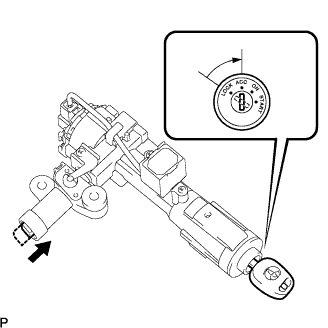
- HINT:
- If there is any abnormality, replace the ignition switch lock cylinder assembly.
| 7. INSTALL STEERING COLUMN UPPER WITH SWITCH BRACKET ASSEMBLY |
Temporarily install the steering column upper with switch bracket assembly with 2 new tapered-head bolts.
Tighten the 2 tapered-head bolts until the bolt heads break off.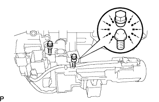
| 8. INSTALL TRANSPONDER KEY AMPLIFIER |
Align the transponder key amplifier with the installation position of the upper bracket with the amplifier inclined.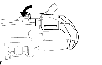
Push the transponder key amplifier up and install it to the upper bracket.
- NOTICE:
- Do not push the amplifier up with excessive force.