INSTALLATION
Removal / installation
| 1. INSTALL POWER STEERING LINK ASSEMBLY |

Install the power steering link assembly with the 2 bolts and 2 nuts.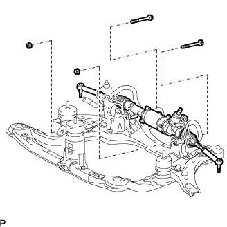

- Torque:
- 70 N*m{ 714 kgf*cm , 52 ft.*lbf }
- NOTICE:
- Turn the bolt while holding the nut.
| 2. INSTALL ENGINE ASSEMBLY WITH TRANSAXLE |
- HINT:
- Refer to the instructions for installation of the engine assembly (Click here).
| 3. CONNECT TIE ROD ASSEMBLY LH |
Connect the tie rod assembly LH to the steering knuckle with the nut.
- Torque:
- 49 N*m{ 500 kgf*cm , 36 ft.*lbf }
Install a new cotter pin.
- NOTICE:
- Further tighten the nut up to 60° if the holes for the cotter pin are not aligned.
| 4. CONNECT TIE ROD ASSEMBLY RH |
- HINT:
- Perform the same procedure as for the LH side.
| 5. CONNECT STEERING INTERMEDIATE SHAFT SUB-ASSEMBLY |
Align matchmarks on the steering intermediate shaft sub-assembly and the power steering link assembly.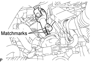
Install the bolt.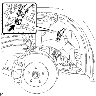
- Torque:
- 35 N*m{ 360 kgf*cm , 26 ft.*lbf }
Tighten the bolt (B).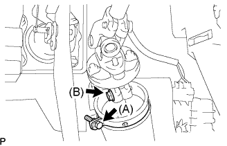
- Torque:
- 35 N*m{ 360 kgf*cm , 26 ft.*lbf }
Install the clamp to the steering column hole shield and tighten the bolt (A).
| 6. INSTALL FRONT STABILIZER LINK ASSEMBLY LH |
Install the front stabilizer link assembly with the nut.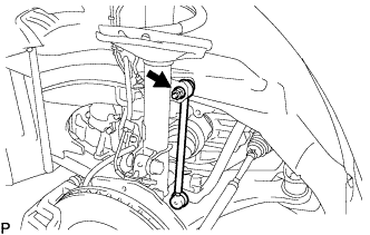
- Torque:
- 74 N*m{ 755 kgf*cm , 55 ft.*lbf }
- HINT:
- If the ball joint turns together with the nut, use a hexagon wrench (6 mm) to hold the stud.
| 7. INSTALL FRONT STABILIZER LINK ASSEMBLY RH |
- HINT:
- Perform the same procedure as for the LH side.
| 8. INSTALL ENGINE UNDER COVER NO.2 |
| 9. INSTALL FRONT WHEELS |
- Torque:
- 103 N*m{ 1,050 kgf*cm , 76 ft.*lbf }
| 10. CONNECT CABLE TO NEGATIVE BATTERY TERMINAL |
| 11. PLACE FRONT WHEELS FACING STRAIGHT AHEAD |
| 12. INSPECT AND ADJUST FRONT WHEEL ALIGNMENT |
| 13. PERFORM INITIALIZATION |
Some systems need initialization when disconnecting the cable from the negative battery terminal (Click here).
| 14. INITIALIZE ROTATION ANGLE SENSOR AND CALIBRATE TORQUE SENSOR ZERO POINT |