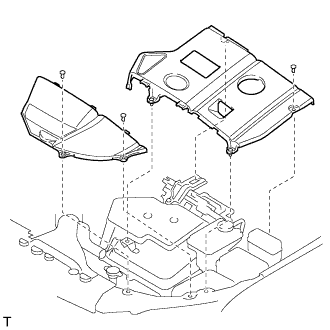
INSTALLATION
Removal / installation
| 1. INSTALL KNOCK CONTROL SENSOR |

Install the 2 knock sensors so that it is horizontal as shown in the illustration. Then install the 2 bolts.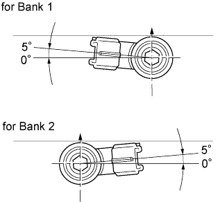

- Torque:
- 20 N*m{ 199 kgf*cm , 15 ft.*lbf }
- HINT:
- It is acceptable for the sensor to be tilted 5°.
Connect the 2 knock sensor connectors.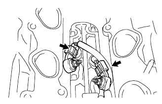
| 2. INSTALL ENGINE OIL PRESSURE SWITCH ASSEMBLY |
Apply adhesive to 2 or 3 threads of the oil pressure switch.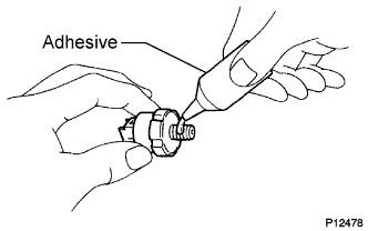
- Adhesive:
- Part No.08833-00080 THREE BOND 1344,
- LOCTITE 242 or equivalent.
Using a deep socket wrench 24 mm, install the oil pressure switch.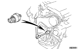
- Torque:
- 15 N*m{ 153 kgf*cm , 11 ft.*lbf }
| 3. INSTALL THERMOSTAT |
Install a new gasket to the thermostat.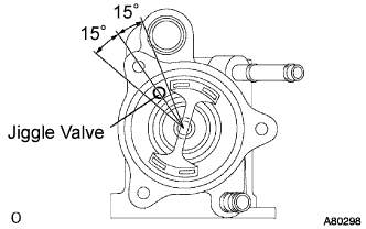
Align the jiggle valve of the thermostat and water inlet, and insert the thermostat in the water inlet housing.
- HINT:
- The jiggle valve should be set within +-15° from the prescribed position.
| 4. INSTALL WATER INLET |
Install the 3 nuts and the water inlet with the 3 nuts.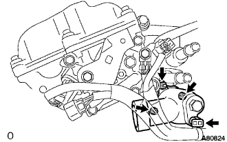
- Torque:
- 8.0 N*m{ 82 kgf*cm , 71 in.*lbf }
| 5. INSTALL WATER INLET PIPE |
Install a new O-ring to the water inlet pipe.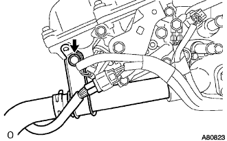
Apply soapy water to the O-ring.
Connect the water inlet pipe to the water inlet.
Install the bolt which is used to fix the water inlet pipe to the cylinder head with the bolt.
- Torque:
- 20 N*m{ 204 kgf*cm , 15 ft.*lbf }
| 6. INSTALL INTAKE AIR CONNECTOR BRACKET NO.2 |
Install the intake air connector bracket No.2 with the 2 bolts. Using several steps, tighten the bolts uniformly in the sequence shown in the illustration.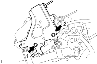
- Torque:
- 7.0 N*m{ 71 kgf*cm , 62 in.*lbf }
| 7. INSTALL COMPRESSOR MOUNTING BRACKET NO.1 |
Temporarily install the mounting bracket with the 4 bolts.
Install the mounting bracket by tightening the 4 bolts in the order shown in the illustration.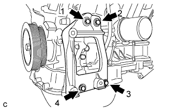
| 8. INSTALL ENGINE MOUNTING STAY BRACKET |
Install the 3 bolts, nut and engine mounting stay bracket.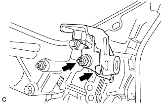
- Torque:
- 52 N*m{ 530 kgf*cm , 38 ft.*lbf }
| 9. INSTALL ENGINE MOUNTING BRACKET RH |
Install the 3 bolts and engine mounting bracket RH.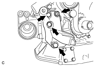
- Torque:
- 54 N*m{ 551 kgf*cm , 40 ft.*lbf }
| 10. INSTALL ENGINE MOUNTING BRACKET REAR |
Install the 3 bolts and engine mounting bracket rear.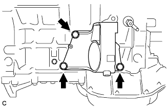
- Torque:
- 64 N*m{ 653 kgf*cm , 47 ft.*lbf }
| 11. INSTALL MANIFOLD STAY NO.2 |
Install the 2 bolts and manifold stay No.2.
- Torque:
- 49 N*m{ 500 kgf*cm , 36 ft.*lbf }
| 12. INSTALL EXHAUST MANIFOLD CONVERTER SUB-ASSEMBLY NO.2 |
Install a new gasket as shown in the illustration.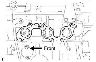
Install the exhaust manifold converter No.2 with the 6 nuts and bolt. Using several steps, tighten the nuts uniformly in the sequence shown in the illustration.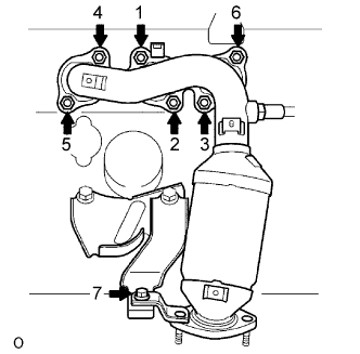
- Torque:
- 49 N*m{ 500 kgf*cm , 36 ft.*lbf }
Retighten nuts 1 and 2 shown in the illustration.
| 13. INSTALL EXHAUST MANIFOLD HEAT INSULATOR NO.2 |
Install the 2 bolts and exhaust manifold heat insulator No.2.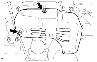
- Torque:
- 8.5 N*m{ 87 kgf*cm , 75 in.*lbf }
| 14. INSTALL MANIFOLD CONVERTER INSULATOR NO.3 |
Install the bolt, nut and manifold converter insulator No.3.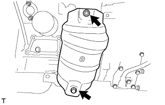
- Torque:
- 8.5 N*m{ 87 kgf*cm , 75 in.*lbf }
| 15. INSTALL IGNITION COIL ASSEMBLY |
- Torque:
- 8.0 N*m{ 80 kgf*cm , 71 in.*lbf }
| 16. INSTALL WATER OUTLET |
Install 2 new gaskets to the 2 cylinder heads.
Install the water outlet together with water by-pass hose No.1 and unlock the hose clamp.
Tighten the 2 bolts, 2 nuts and 2 washers.
- Torque:
- 15 N*m{ 153 kgf*cm , 11 ft.*lbf }
Install the clamp.
Connect the engine coolant temperature sensor connector.
Connect the radiator hose inlet.
| 17. INSTALL INTAKE MANIFOLD |
Install the intake manifold with the 9 bolts, 2 nuts and 2 washers. Using several steps, tighten the bolts and nuts uniformly in the sequence shown in the illustration.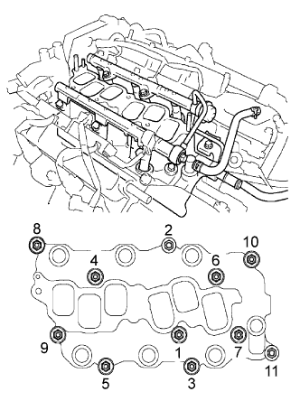
- Torque:
- 15 N*m{ 153 kgf*cm , 11 ft.*lbf }
Retighten the water outlet mounting bolts and nuts.
- Torque:
- 15 N*m{ 153 kgf*cm , 11 ft.*lbf }
Install the ground cable with the nut.
- Torque:
- 8.4 N*m{ 86 kgf*cm , 74 in.*lbf }
Connect the heater inlet water hose.
| 18. INSTALL INTAKE AIR SURGE TANK |
Install a new gasket to the intake air surge tank.
Using a socket hexagon wrench 8 mm, install the intake manifold with the 4 bolts and 2 nuts . Using several steps, tighten the bolts and nuts uniformly in the sequence shown in the illustration.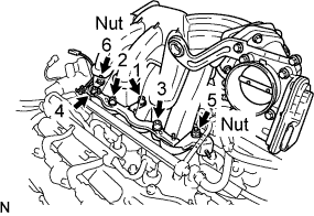
- Torque:
- 28 N*m{ 286 kgf*cm , 21 ft.*lbf }
Connect the ground cable connector.
Install the surge tank stay No. 2 (A) with the 2 bolts.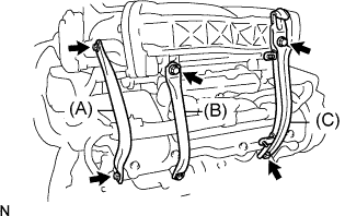
- Torque:
- 20 N*m{ 199 kgf*cm , 14 ft.*lbf }
Install the surge tank stay No. 1 (B) with the 2 bolts.
- Torque:
- 20 N*m{ 199 kgf*cm , 14 ft.*lbf }
Install the engine hunger No. 1 (C) with the 2 bolts.
- Torque:
- 20 N*m{ 199 kgf*cm , 14 ft.*lbf }
Connect the ventilation hose.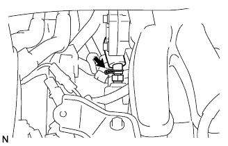
Connect the fuel vapor feed hose (A).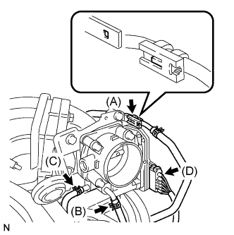
Connect the water by-pass hose No.3 (B).
Connect the water by-pass hose No.2 (C).
Connect the throttle motor connector (D).
| 19. INSTALL EMISSION CONTROL VALVE SET |
Install the emission control valve set with the 2 nuts (A).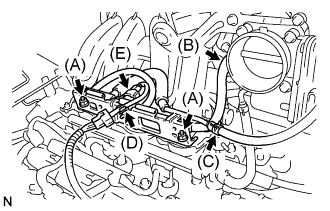
- Torque:
- 8.0 N*m{ 82 kgf*cm , 71 in.*lbf }
Connect the fuel vapor feed hose No.2 (B).
Connect the fuel vapor feed hose No.1 (C).
Connect the wire harness clamp (D).
Connect the VSV connector (E).
| 20. INSTALL ENGINE HANGER NO.2 |
Install the No.2 engine hanger in the correct direction shown in the illustration.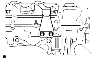
- Torque:
- 20 N*m{ 199 kgf*cm , 14 ft.*lbf }
| 21. REMOVE ENGINE STAND |
| 22. INSTALL FLYWHEEL SUB-ASSEMBLY |
Using SST, hold the crankshaft.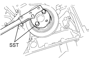
- SST
- 09213-54015
(91651-60855)
09330-00021
Clean the bolts and bolt holes.
Apply adhesive to 2 or 3 threads of the bolts.
- Adhesive:
- Part No.08833-00070, THREE BOND 1324 or equivalent
Install the flywheel on the crankshaft.
Using several steps, install and tighten the 8 bolts uniformly in the sequence shown in the illustration.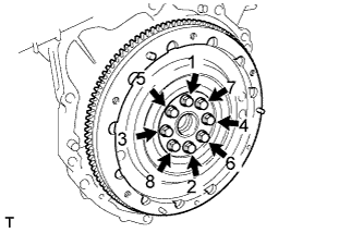
- Torque:
- 83 N*m{ 846 kgf*cm , 61 ft.*lbf }
- NOTICE:
- Do not start the engine within 1 hour after installing.
| 23. INSTALL TRANSMISSION INPUT DAMPER ASSEMBLY |
Using SST, hold the crankshaft.
- SST
- 09213-54015
(91651-60855)
09330-00021
Install the 6 bolts and transmission input damper.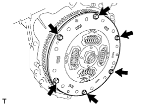
- Torque:
- 30 N*m{ 306 kgf*cm , 22 ft.*lbf }
- HINT:
- Take care not to insert the transmission input damper in the wrong direction.
| 24. INSTALL HYBRID VEHICLE TRANSAXLE ASSEMBLY |
Make sure that the knock pins are installed on the engine.
Install the hybrid vehicle transaxle and the 8 bolts shown in the illustration to the engine.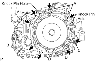
- Torque:
- Bolt A:
- 64 N*m{ 653 kgf*cm , 47 ft.*lbf }
- Torque:
- Bolt B:
- 46 N*m{ 469 kgf*cm , 34 ft.*lbf }
- Torque:
- Bolt C:
- 64 N*m{ 653 kgf*cm , 47 ft.*lbf }
- Torque:
- Bolt D:
- 37 N*m{ 377 kgf*cm , 27 ft.*lbf }
- NOTICE:
- Do not reuse bolt B.
- Do not forcibly pry out the hybrid vehicle transaxle assembly
- Do not apply the grease either to the spline or to the input shaft.
- Do not reuse bolt B.
Bolt
Installation direction
Diameter
Bolt length
A
From transaxle to engine
12 mm (0.47 in.)
55 mm (2.17 in.)
B
From engine to transaxle
10 mm (0.39 in.)
55 mm (2.17 in.)
C
From transaxle to engine
12 mm (0.47 in.)
55 mm (2.17 in.)
D
From engine to transaxle
10 mm (0.39 in.)
33 mm (1.30 in.)
| 25. INSTALL ENGINE MOUNTING BRACKET FRONT |
Install the engine mounting bracket front with the 3 bolts.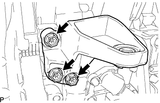
- Torque:
- 64 N*m{ 653 kgf*cm , 47 ft.*lbf }
| 26. INSTALL FLYWHEEL HOUSING UNDER COVER |
Install the flywheel housing under cover with the 2 bolts.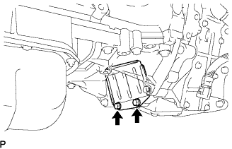
- Torque:
- 7.8 N*m{ 80 kgf*cm , 69 in.*lbf }
| 27. INSTALL FRONT DRIVE SHAFT ASSEMBLY LH |
Install a new drive shaft hole snap ring.
Coat the spline of the inboard joint shaft assembly with ATF.
Align the shaft splines and install the drive shaft assembly with a brass bar and a hammer.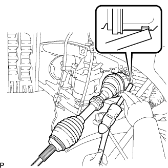
- NOTICE:
- Set the snap ring with the opening side facing down.
- Be careful not to damage the drive shaft dust cover, boot, or oil seal.
- Set the snap ring with the opening side facing down.
| 28. INSTALL FRONT DRIVE SHAFT ASSEMBLY RH |
Coat the spline of the inboard joint shaft assembly with ATF.
Align the shaft splines and install the drive shaft assembly.
- NOTICE:
- Be careful not to damage the drive shaft dust cover, boot, or oil seal.
Using pliers, install a new bearing bracket hole snap ring.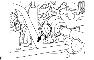
Install a new bolt to the drive shaft bearing bracket.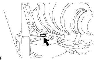
- Torque:
- 32 N*m{ 330 kgf*cm , 24 ft.*lbf }
| 29. INSTALL FRONT FRAME ASSEMBLY |
Install the engine mounting insulators RH and LH with the 2 nuts.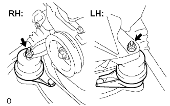
- Torque:
- 95 N*m{ 969 kgf*cm , 70 ft.*lbf }
Install the engine mounting insulator FR with the nut.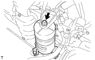
- Torque:
- 87 N*m{ 887 kgf*cm , 64 ft.*lbf }
Install the engine mounting insulator RR with the 2 bolts.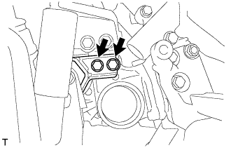
- Torque:
- 75 N*m{ 765 kgf*cm , 55 ft.*lbf }
| 30. INSTALL HV TRANSAXLE MASS DAMPER |
Install the bolt and transaxle mass damper.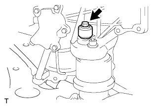
- Torque:
- 14 N*m{ 138 kgf*cm , 10 ft.*lbf }
| 31. INSTALL EXHAUST MANIFOLD SUB-ASSEMBLY RH |
Install a new gasket as shown in the illustration.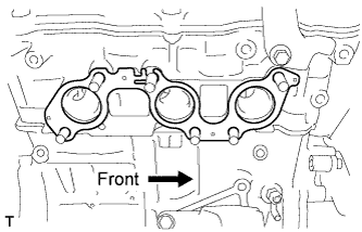
Install a new gasket and the exhaust manifold RH with the 6 nuts. Using several steps, tighten the nuts uniformly in the sequence shown in the illustration.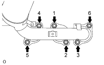
- Torque:
- 49 N*m{ 500 kgf*cm , 36 ft.*lbf }
Retighten nuts 1 and 2 shown in the illustration.
| 32. INSTALL MANIFOLD STAY |
Temporarily install the manifold stay to the exhaust manifold and transaxle.
Fully tighten the 2 bolts.
- Torque:
- 34 N*m{ 347 kgf*cm , 25 ft.*lbf }
| 33. INSTALL EXHAUST MANIFOLD HEAT INSULATOR NO.1 |
Install the 3 bolts and exhaust manifold heat insulator No.1.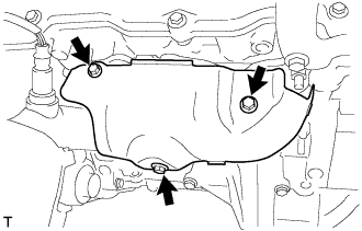
- Torque:
- 8.5 N*m{ 87 kgf*cm , 75 in.*lbf }
| 34. INSTALL ENGINE WIRE |
| 35. INSTALL ENGINE ASSEMBLY WITH TRANSAXLE |
Set the engine assembly with transaxle on the engine lifter.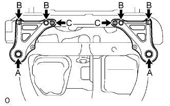
Install the engine assembly to the vehicle.
Install the frame side rail plates RH and LH with the 6 bolts and 2 nuts.
- Torque:
- Bolt A:
- 85 N*m{ 867 kgf*cm , 63 ft.*lbf }
- Bolt B:
- 32 N*m{ 326 kgf*cm , 24 ft.*lbf }
- Nut C:
- 32 N*m{ 326 kgf*cm , 24 ft.*lbf }
Install the front suspension member brace rear RH and LH with the 6 bolts and 2 nuts.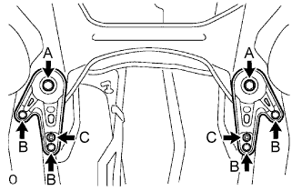
- Torque:
- Bolt A:
- 85 N*m{ 867 kgf*cm , 63 ft.*lbf }
- Bolt B:
- 32 N*m{ 326 kgf*cm , 24 ft.*lbf }
- Nut C:
- 32 N*m{ 326 kgf*cm , 24 ft.*lbf }
| 36. CONNECT STEERING INTERMEDIATE SHAFT SUB-ASSEMBLY |
Align matchmarks on the steering intermediate shaft sub-assembly and the power steering link assembly.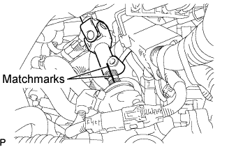
Install the bolt.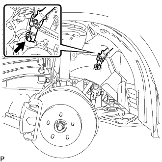
- Torque:
- 35 N*m{ 360 kgf*cm , 26 ft.*lbf }
Tighten the bolt (B).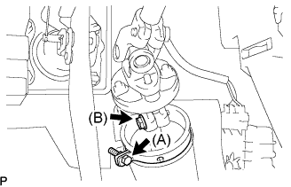
- Torque:
- 35 N*m{ 360 kgf*cm , 26 ft.*lbf }
Install the clamp to the steering column hole shield and tighten the bolt (A).
| 37. INSTALL FRONT AXLE ASSEMBLY LH |
Install the drive shaft assembly LH to the front axle assembly LH.
- NOTICE:
- Be careful not to damage the outboard joint boot.
- Be careful not to damage the speed sensor rotor.
- Be careful not to damage the outboard joint boot.
| 38. INSTALL FRONT AXLE ASSEMBLY RH |
- HINT:
- Perform the same procedure as above on the opposite side.
| 39. INSTALL FRONT SUSPENSION ARM SUB-ASSEMBLY LOWER NO.1 LH |
Install the lower ball joint to the front suspension arm sub-assembly lower with the bolt and 2 nuts.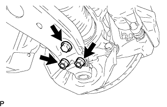
- Torque:
- 127 N*m{ 1,300 kgf*cm , 94 ft.*lbf }
| 40. INSTALL FRONT SUSPENSION ARM SUB-ASSEMBLY LOWER NO.1 RH |
- HINT:
- Perform the same procedure as above on the opposite side.
| 41. CONNECT TIE ROD END SUB-ASSEMBLY LH |
Connect the tie rod assembly LH to the steering knuckle with the nut.
- Torque:
- 49 N*m{ 500 kgf*cm , 36 ft.*lbf }
Install a new cotter pin.
- NOTICE:
- Further tighten the nut up to 60° if the holes for the cotter pin are not aligned.
| 42. CONNECT TIE ROD END SUB-ASSEMBLY RH |
- HINT:
- Perform the same procedure as above on the opposite side.
| 43. INSTALL SPEED SENSOR FRONT LH |
Install the speed sensor to the steering knuckle with the bolt.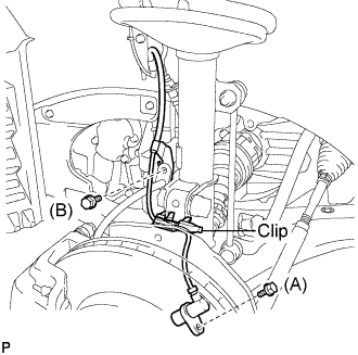
- Torque:
- Bolt A:
- 8.0 N*m{ 82 kgf*cm , 71 in.*lbf }
- NOTICE:
- Be careful not to damage the speed sensor.
- Prevent foreign matter from attaching to the speed sensor.
- Do not twist the sensor wire when installing the speed sensor.
- Be careful not to damage the speed sensor.
Install the flexible hose and the speed sensor to the shock absorber with the bolt and set the clip of sensor on the knuckle.
- Torque:
- Bolt B:
- 19 N*m{ 192 kgf*cm , 14 ft.*lbf }
| 44. INSTALL SPEED SENSOR FRONT RH |
- HINT:
- Perform the same procedure as above on the opposite side.
| 45. INSTALL FRONT AXLE HUB LH NUT |
Using a socket wrench (30 mm), install a new axle hub nut.
- Torque:
- 294 N*m{ 3,000 kgf*cm , 217 ft.*lbf }
- NOTICE:
- Stake the nut after inspecting for looseness and runout in the following steps.
| 46. INSTALL FRONT AXLE HUB RH NUT |
- HINT:
- Perform the same procedure as above on the opposite side.
| 47. INSTALL FRONT STABILIZER LINK ASSEMBLY LH |
Install the front stabilizer link assembly with the nut.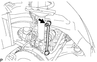
- Torque:
- 74 N*m{ 755 kgf*cm , 55 ft.*lbf }
- HINT:
- If the ball joint turns together with the nut, use a hexagon wrench (6 mm) to hold the stud.
| 48. INSTALL FRONT STABILIZER LINK ASSEMBLY RH |
- HINT:
- Perform the same procedure as above on the opposite side.
| 49. INSTALL EXHAUST PIPE SUB-ASSEMBLY FRONT NO.3 |
Using vernier calipers, measure the free length of the compression spring.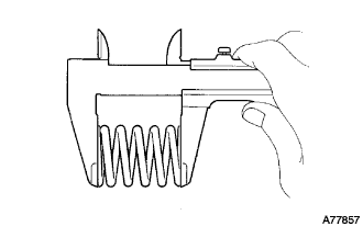
- Minimum length:
- 41.5 mm (1.634 in.)
- HINT:
- If the free length is less than the minimum, replace the compression spring.
Install a new gasket to the exhaust pipe front No. 3 as shown in the illustration.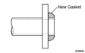
Install 2 new gaskets and the exhaust pipe front No. 3 with the 2 bolts and 2 new nuts.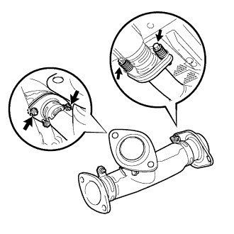
- Torque:
- Bolt:
- 48 N*m{ 490 kgf*cm , 35 ft.*lbf }
- Nut:
- 56 N*m{ 571 kgf*cm , 41 ft.*lbf }
Connect the heated oxygen sensor connector.
| 50. INSTALL EXHAUST PIPE ASSEMBLY FRONT |
Install 2 new gaskets and the exhaust pipe front No. 3 with the 2 bolts and 2 new nuts.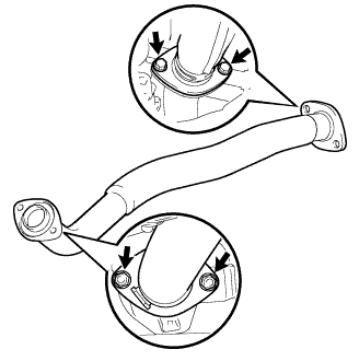
- Torque:
- 56 N*m{ 571 kgf*cm , 41 ft.*lbf }
Connect the heated oxygen sensor connector.
| 51. CONNECT WIRE HARNESS |
Connect the power steering link connector and clamp.
Install the ground cable.
| 52. CONNECT ENGINE WIRE |
Install the 2 nuts and pull in the engine wire harness.
- Torque:
- 8.4 N*m{ 85 kgf*cm , 74 in.*lbf }
Connect the engine wire harness to the ECM and the junction block.
Install the body ground and connector.
| 53. INSTALL GLOVE COMPARTMENT DOOR ASSEMBLY |
Connect the connectors.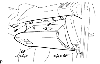
Install the 2 bolts <A>, the 2 screws <C>, and the glove compartment door assembly.
| 54. INSTALL INSTRUMENT PANEL NO.2 UNDER COVER SUB-ASSEMBLY |
Connect the connectors.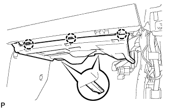
Engage the 3 claws and install the instrument panel No.2 under cover sub-assembly.
| 55. CONNECT WATER HOSE |
| 56. INSTALL HEATER WATER PUMP ASSEMBLY |
Install the bolt and heater water pump assembly.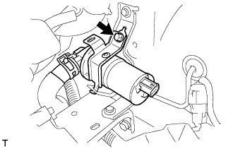
- Torque:
- 5.4 N*m{ 55 kgf*cm , 48 in.*lbf }
| 57. CONNECT OIL COOLER INLET TUBE SUB-ASSEMBLY |
Using pliers, grip the claws of the clip and slide the clip to connect the oil cooler inlet tube.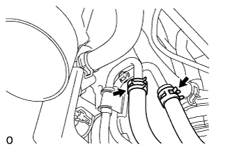
| 58. CONNECT OIL COOLER OUTLET TUBE SUB-ASSEMBLY |
- HINT:
- Connection of the oil cooler outlet tube is the same as for the oil cooler inlet tube.
| 59. CONNECT RADIATOR HOSE INLET |
| 60. CONNECT RADIATOR HOSE OUTLET |
| 61. CONNECT HEATER WATER INLET HOSE |
Using pliers, grip the claws of the clip and slide the clip to connect the heater water inlet hose.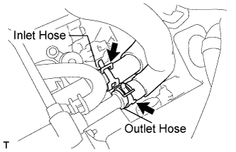
| 62. CONNECT HEATER WATER OUTLET HOSE |
- HINT:
- Connection of the heater water outlet hose is the same as for the heater water inlet hose.
| 63. CONNECT FUEL PIPE SUB-ASSEMBLY NO.1 |
Align the connector with the pipe, then push in the connector to the pipe until it makes a "click" sound to connect the fuel tube sub-assembly to the fuel delivery pipe.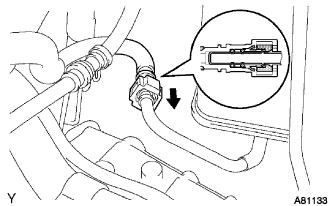
Install the EFI fuel pipe clamp.
| 64. INSTALL TRANSMISSION CONTROL CABLE ASSEMBLY |
Install the control cable to the transaxle with the bolt.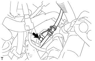
- Torque:
- 12 N*m{ 120 kgf*cm , 9 ft.*lbf }
Install the control shaft lever with the nut.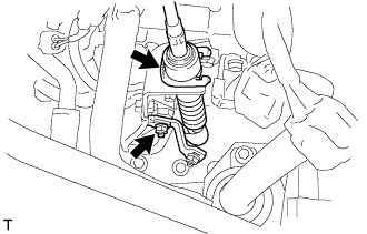
- Torque:
- 6.9 N*m{ 70 kgf*cm , 61 in.*lbf }
Install the control cable and a new clip to the bracket.
| 65. INSTALL INVERTER BRACKET NO.1 |
Install the 4 bolts and inverter bracket.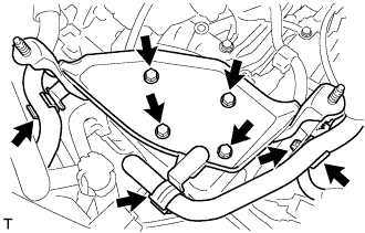
- Torque:
- 21 N*m{ 214 kgf*cm , 15 ft.*lbf }
Install the harness clamp and hose clamp.
| 66. INSTALL COMPRESSOR W/ MOTOR ASSEMBLY |
Temporarily install the compressor and magnetic clutch with the 3 bolts.
Install the compressor and magnetic clutch by tightening the 3 bolts in the order shown in the illustration.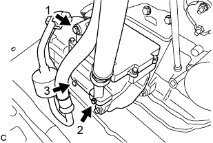
- Torque:
- 25 N*m{ 250 kgf*cm , 18 ft.*lbf }
Connect the 2 connectors.
| 67. INSTALL ENGINE MOUNTING STAY NO.2 RH |
Install the engine mounting stay No.2 and the engine mounting bracket No.2 with the bolt.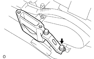
- Torque:
- 64 N*m{ 653 kgf*cm , 47 ft.*lbf }
| 68. INSTALL ENGINE MOVING CONTROL ROD |
Temporarily tighten bolts B and C.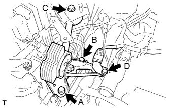
First tighten bolt A, bolt B, then bolt C in this order.
- Torque:
- 64 N*m{ 653 kgf*cm , 47 ft.*lbf }
Tighten bolt D.
- Torque:
- 23 N*m{ 235 kgf*cm , 17 ft.*lbf }
| 69. INSTALL AIR CLEANER BRACKET |
Install the 2 bolts and air cleaner bracket.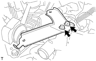
- Torque:
- 27 N*m{ 275 kgf*cm , 20 ft.*lbf }
| 70. INSTALL RESERVOIR BRACKET |
Install the 2 bolts, nut and reservoir bracket.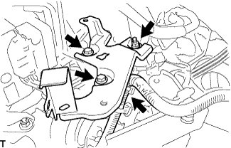
- Torque:
- 9.0 N*m{ 92 kgf*cm , 80 in.*lbf }
Connect the clamp.
| 71. INSTALL BRAKE MASTER CYLINDER RESERVOIR SUB-ASSEMBLY |
Install the 2 bolts and brake master cylinder reservoir to the bracket.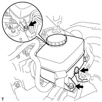
- Torque:
- 9.0 N*m{ 92 kgf*cm , 80 in.*lbf }
Connect the connector.
| 72. INSTALL W/ CONVERTER INVERTER ASSEMBLY |
- CAUTION:
- Wear insulating gloves.
Install the w/ converter inverter assembly with the 2 nuts and bolt.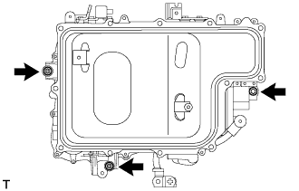
- Torque:
- 21 N*m{ 214 kgf*cm , 15 ft.*lbf }
- NOTICE:
- 2 people are needed to install the w/ converter inverter assembly.
| 73. INSTALL INVERTER BRACKET NO.4 |
Install the inverter bracket No.4 with the 2 bolts.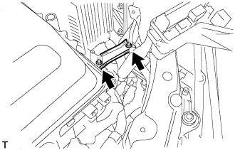
- Torque:
- 21 N*m{ 214 kgf*cm , 15 ft.*lbf }
| 74. INSTALL ENGINE ROOM RELAY BLOCK ASSEMBLY |
Install the engine room relay block assembly.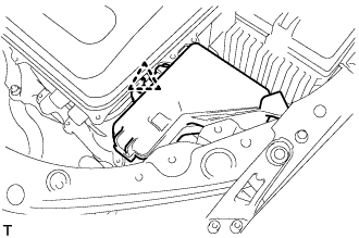
| 75. REMOVE INVERTER COVER |
Remove the 2 bolts and inverter cover to the w/ converter inverter assembly.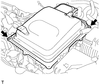
| 76. INSTALL NO.3 WIRE FRAME |
- CAUTION:
- Wear insulating gloves.
- NOTICE:
- Make sure that the inverter converter is temporarily installed before working on the converter inverter assembly. (Click here)
- Do not allow any foreign objects or waterdrops to enter the w/ converter inverter assembly.
- Make sure that the inverter converter is temporarily installed before working on the converter inverter assembly. (Click here)
After connecting the connector, press the lever down to connect the No.3 wire frame and install the bolt to the w/ converter inverter assembly.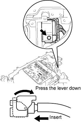
- Torque:
- 10 N*m{ 102 kgf*cm , 7 ft.*lbf }
Connect the No.3 wire frame (high voltage cable of the rear motor) with the 5 bolts to the w/ converter inverter assembly.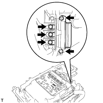
- Torque:
- 10 N*m{ 102 kgf*cm , 7 ft.*lbf }
| 77. INSTALL MG ECU CONNECTOR |
- CAUTION:
- Wear insulating gloves.
- NOTICE:
- Make sure that the inverter converter is temporarily installed before working on the converter inverter assembly. (Click here)
- Do not allow any foreign objects or waterdrops to enter the w/ converter inverter assembly.
- Make sure that the inverter converter is temporarily installed before working on the converter inverter assembly. (Click here)
Connect the 2 connectors and 2 grommets to the w/ converter inverter assembly.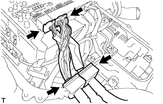
| 78. CONNECT HIGH VOLTAGE CABLE OF FRONT MOTOR |
- CAUTION:
- Wear insulating gloves.
- NOTICE:
- Make sure that the inverter converter is temporarily installed before working on the converter inverter assembly. (Click here)
- Do not allow any foreign objects or waterdrops to enter the w/ converter inverter assembly.
- Make sure that the inverter converter is temporarily installed before working on the converter inverter assembly. (Click here)
Connect the high voltage cable of the Generator with the 5 bolts to the w/ converter inverter assembly.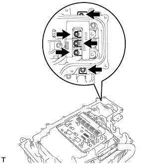
- Torque:
- 10 N*m{ 102 kgf*cm , 7 ft.*lbf }
Connect the high voltage cable of the Motor with the 5 bolts to the w/ converter inverter assembly.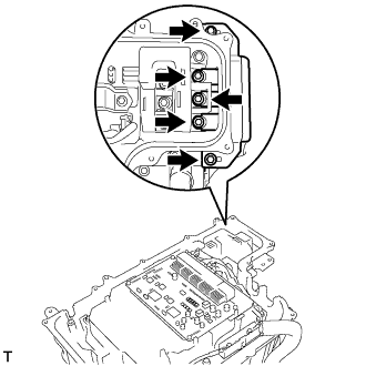
- Torque:
- 10 N*m{ 102 kgf*cm , 7 ft.*lbf }
| 79. INSTALL ENGINE WIRE NO.4 |
- CAUTION:
- Wear insulating gloves.
- NOTICE:
- Make sure that the inverter converter is temporarily installed before working on the converter inverter assembly. (Click here)
- Do not allow any foreign objects or waterdrops to enter the w/ converter inverter assembly.
- Make sure that the inverter converter is temporarily installed before working on the converter inverter assembly. (Click here)
Connect the engine wire No.4 with the connector, clamp and grommet to the w/ converter inverter assembly.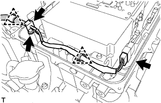
Connect the engine wire No.4 with the bolt to the w/ converter inverter assembly.
- Torque:
- 5.4 N*m{ 55 kgf*cm , 48 in.*lbf }
| 80. CHECK HIGH VOLTAGE CABLE CONNECTION |
- CAUTION:
- Wear insulating gloves.
- NOTICE:
- Make sure that the inverter converter is temporarily installed before working on the converter inverter assembly. (Click here)
- Do not allow any foreign objects or waterdrops to enter the w/ converter inverter assembly.
- Make sure that the inverter converter is temporarily installed before working on the converter inverter assembly. (Click here)
Check that each connector and terminal is firmly installed.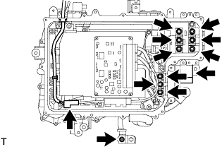
- NOTICE:
- Make sure that the connectors are fully engaged.
- Make sure that the bolts are fully tightened.
- Make sure that the connectors are fully engaged.
| 81. INSTALL INVERTER COVER |
Install the inverter cover with the 12 bolts to the w/ converter inverter assembly.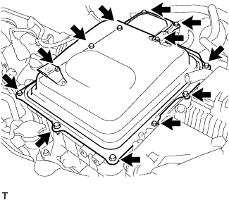
- Torque:
- 10 N*m{ 102 kgf*cm , 7 ft.*lbf }
Install the interlock bracket with the bolt to the w/ converter inverter assembly.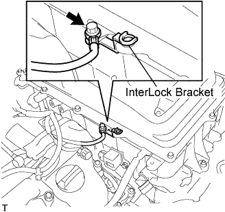
- Torque:
- 10 N*m{ 102 kgf*cm , 7 ft.*lbf }
| 82. INSTALL POWER STEERING ECU BRACKET |
Install the power steering ECU bracket with the bolt to the w/ converter inverter assembly.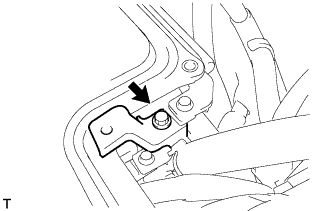
- Torque:
- 8.0 N*m{ 82 kgf*cm , 71 in.*lbf }
| 83. CONNECT WATER HOSE |
Connect the water hose with the clamp to the w/ converter inverter assembly.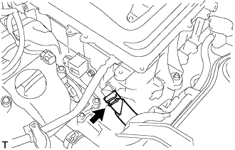
| 84. INSTALL INVERTER RESERVE TANK SUB-ASSEMBLY |
Connect the 2 water hoses with the 2 clamps to the inverter reserve tank sub-assembly.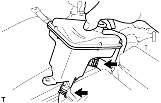
Install the inverter reserve tank with the 2 bolts to the w/ converter inverter assembly.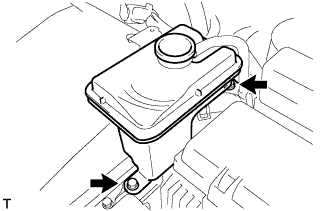
- Torque:
- 10 N*m{ 102 kgf*cm , 7 ft.*lbf }
| 85. CONNECT ENGINE ROOM WIRE NO.2 |
Connect the engine room wire No.2 with the nut.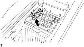
- Torque:
- 8.5 N*m{ 87 kgf*cm , 75 in.*lbf }
| 86. CONNECT CIRCUIT BREAKER SENSOR NO.1 |
Connect the circuit breaker sensor No.1 connector.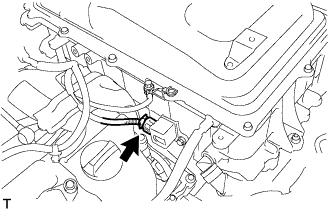
| 87. INSTALL POWER STEERING ECU ASSEMBLY |
Install the power steering ECU assembly with the 2 bolts.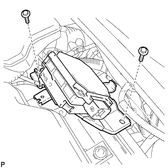
- Torque:
- 8.0 N*m{ 82 kgf*cm , 71 in.*lbf }
Connect the 2 wire harness clamps to the power steering ECU assembly.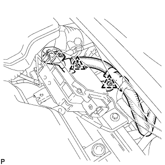
Connect the 2 power steering ECU assembly connectors and securely lock the connectors.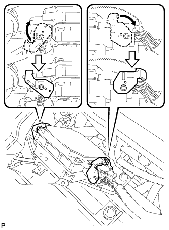
Install the ground cable terminal to the power steering ECU assembly with the bolt.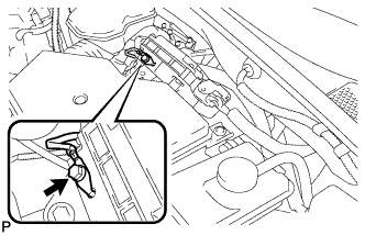
- Torque:
- 6.0 N*m{ 61 kgf*cm , 53 in.*lbf }
| 88. INSTALL INVERTER BRACKET NO.5 |
Install the inverter bracket No.5 with the bolt.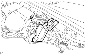
- Torque:
- 10 N*m{ 102 kgf*cm , 7 ft.*lbf }
| 89. INSTALL AIR CLEANER CASE W/ RESONATOR |
Install the air cleaner hose No.1 to the throttle body assembly with the hose clamp.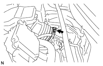
Install the air cleaner case w/ resonator with the 5 bolts.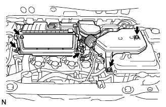
- Torque:
- 5.0 N*m{ 51 kgf*cm , 44 in.*lbf }
Connect the MAF meter connector.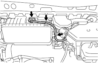
Connect the 2 wire harness clamps to the air cleaner.
Connect the ventilation hose No.2.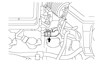
| 90. INSTALL AIR CLEANER CAP W/ INLET |
Install the air cleaner filter element to the air cleaner case.
Install the 2 bolts, 4 clamps and air cleaner cap w/ inlet.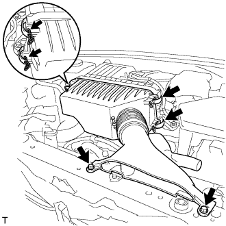
- Torque:
- 7.0 N*m{ 71 kgf*cm , 62 in.*lbf }
| 91. INSTALL COOL AIR INTAKE DUCT SEAL |
Install the 4 clips and cool air intake duct seal.
| 92. INSTALL BATTERY CARRIER SUB-ASSEMBLY |
Install the 5 bolts and battery carrier.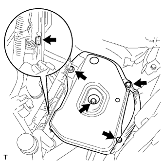
- Torque:
- 19 N*m{ 194 kgf*cm , 14 ft.*lbf }
| 93. INSTALL BATTERY |
Install the battery clamp and battery.
- Torque:
- 5.4 N*m{ 55 kgf*cm , 48 in.*lbf }
| 94. INSTALL SERVICE PLUG GRIP |
- NOTICE:
- Before connecting the service plug, check that no parts and tools remain and that the high voltage terminals and connectors are connected securely.
Wear insulation gloves, then insert the service plug.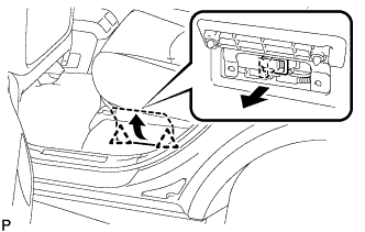
Push down on the grip to lock.
Close the battery service hole cover.
- NOTICE:
- Check that the 2 battery service hole cover clips are securely connected to the battery carrier bracket (click sound).
| 95. INSTALL COWL TOP PANEL SUB-ASSEMBLY OUTER |
Remove the 4 shock absorber nuts.
Install the 4 bolts, 2 nuts and cowl top panel sub-assembly.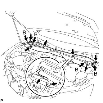
- Torque:
- 5.0 N*m{ 51 kgf*cm , 44 in.*lbf }
Install the 4 shock absorber nuts (B).
- Torque:
- 80 N*m{ 815 kgf*cm , 59 ft.*lbf }
Install the wire harness clamp and grommet (A).
| 96. INSTALL WINDSHIELD WIPER MOTOR AND LINK ASSEMBLY |
Install the windshield wiper motor and link assembly with the 5 bolts.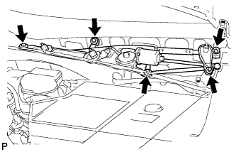
- Torque:
- 7.0 N*m{ 71 kgf*cm , 62 in.*lbf }
Connect the connector.
| 97. INSTALL COWL TOP VENTILATOR LOUVER SUB-ASSEMBLY |
| 98. INSTALL FRONT WIPER ARM AND BLADE ASSEMBLY LH |
Operate the front wiper, and stop the front wiper motor at the automatic stop position.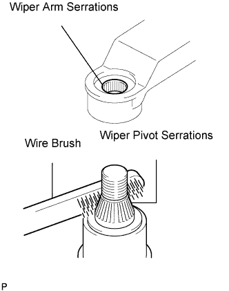
Clean the wiper arm serrations.
Clean the wiper pivot serrations with a wire brush (when reinstalling).
Install the front wiper arm and blade assembly LH with the nut at the position as shown in the illustration.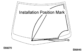
- Torque:
- 24 N*m{ 245 kgf*cm , 18 ft.*lbf }
- HINT:
- Hold the arm hinge by hand to fasten the nut.
| 99. INSTALL FRONT WIPER ARM AND BLADE ASSEMBLY RH |
Clean the wiper arm serrations.
Clean the wiper pivot serrations with a wire brush (when reinstalling).
Install the front wiper arm and blade assembly RH with the 2 nuts at the position as shown in the illustration.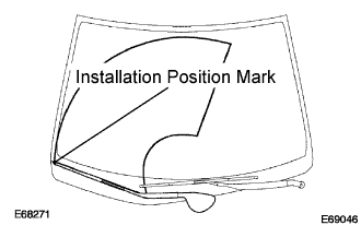
- Torque:
- 24 N*m{ 245 kgf*cm , 18 ft.*lbf }
- HINT:
- Hold the arm hinge by hand to fasten the nut.
Operate the front wipers while spraying water or washer fluid on the windshield.
Make sure that the wipers function properly and there is no interference with the vehicle body.
| 100. INSTALL FRONT WHEELS |
- Torque:
- 103 N*m{ 1,050 kgf*cm , 76 ft.*lbf }
| 101. ADD AND INSPECT HYBRID TRANSAXLE FLUID |
Fill oil.
- Transaxle fluid quantity:
- 4.2 L (4.4 US qts, 3.7 Imp. qts.)
Check that the oil surface is within 5 mm (0.20 in.) from the lowest position of the inner surface of the differential filler plug opening.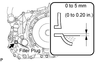
- NOTICE:
- Keep the oil temperature at 5°C (41°F) or higher.
- Stop the vehicle on a flat road.
- Recheck the transaxle oil level after driving when exchanging oil.
- Insufficient or excessive amounts of transaxle oil may be the cause of some trouble.
- Keep the oil temperature at 5°C (41°F) or higher.
Using a socket hexagon wrench 10 mm, temporarily tighten the filler plug and gasket.
Connect the intelligent tester to the DLC3.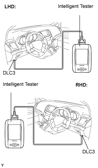
Turn the ignition switch to the ON position.
Select the inspection mode. (Click here)
On the tester, enter the following menus: Powertrain / Hybrid Control / Active test / Inspection Mod 1.
Turn the ignition switch to the ON position and turn the tester on.
- HINT:
- Operate the oil pump for 1 minute.
Using a socket hexagon wrench 10 mm, remove the filler plug and gasket.
Fill oil.
Check that the oil surface is within 5 mm (0.20 in.) from the lowest position of the inner surface of the differential filler plug opening.
- NOTICE:
- Keep the oil temperature at 5°C (41°F) or higher.
- Stop the vehicle on a flat road.
- Recheck the transaxle oil level after driving when exchanging oil.
- Insufficient or excessive amounts of transaxle oil may be the cause of some trouble.
- Keep the oil temperature at 5°C (41°F) or higher.
Check for leaks if the quantity of oil is low.
Using a socket hexagon wrench 10 mm, install the filler plug, and a new gasket.
- Torque:
- 39 N*m{ 398 kgf*cm , 29 ft.*lbf }
| 102. ADD ENGINE OIL |
| 103. CHECK FOR FUEL LEAKS |
Connect the intelligent tester to the DLC3.
Turn the ignition switch to the ON position and turn the intelligent tester on.
- NOTICE:
- Do not start the engine.
Select the Active Test mode on the intelligent tester to operate the fuel pump.
- HINT:
- Refer to the intelligent tester operator's manual for further details.
Check that there are no fuel leaks anywhere in the fuel system after performing maintenance.
| 104. ADD COOLANT (Hybrid side) |
Loosen the bleeder plug shown in the illustration and connect a hose.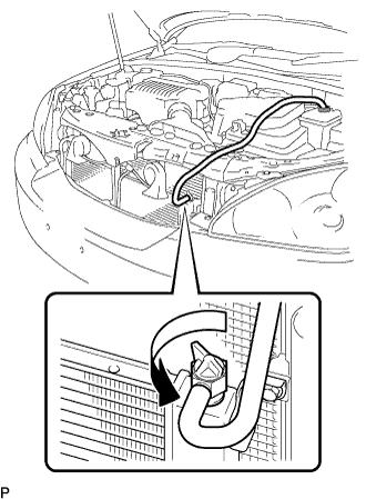
- NOTICE:
- Insert one end of the hose into the reserve tank.
Add coolant from the reserve tank.
Add coolant until the level of coolant in the hose attached to the bleeder plug reaches the same level as the FULL line of the reserve tank.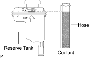
- Coolant quantity:
- 3.4 L (3.6 US qts, 3.0 Imp. qts.)
When using the intelligent tester:
Connect the intelligent tester to the DLC3.
Turn the ignition switch to the ON position.
Select the inspection mode (Click here).
On the tester, enter the following menus: Powertrain / Hybrid Control / Active test / Water Pump.
Keep the coolant at the FULL level in the reserve tank to compensate for the drop in coolant level when the air bleeds.
- Standard:
- Air bleeding from the coolant system is completed when the noise made by the water pump becomes smaller and the circulation of coolant in the reserve tank improves.
- HINT:
- Loud noise made by the water pump and poor circulation of coolant in the reserve tank indicates that there is air in the coolant system.
When not using the intelligent tester:
Put the vehicle into the READY-on state. [*1]
Turn the ignition switch off and add coolant to the FULL level because the coolant level drops as the air bleeds. [*2]
- NOTICE:
- Be sure to turn the ignition switch off before adding LLC.
- Do not work on the components in the engine compartment while the vehicle is in the READY-on state because the engine is in intermittent operation.
- Be sure to turn the ignition switch off before adding LLC.
Repeat steps [*1] and [*2] until air bleeding from the coolant system is completed.
- Standard:
- Air bleeding from the coolant system is completed when the noise made by the water pump becomes smaller and the circulation of coolant in the reserve tank improves.
- HINT:
- Loud noise made by the water pump and poor circulation of coolant in the reserve tank indicates that there is air in the coolant system.
When the air is completely bled from the coolant system, tighten the plug.
Add coolant to the FULL mark of the reserve tank.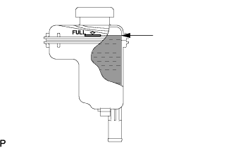
| 105. ADD COOLANT (Engine side) |
Tighten the lower drain plug of the radiator.
Loosen the upper drain plug of the radiator.
Install a vinyl tube to the vent plug located on the upper drain plug.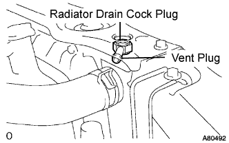
Fill the radiator with engine coolant until the vinyl tube is filled with the coolant.
Tighten the upper drain plug.
- CAUTION:
- Do not use an alcohol type coolant or plain water alone.
- The coolant must be mixed with plain water (preferably de-mineralized water).
- Capacity:
- 9.7 liters (10.3 US qts, 8.5 lmp.qts)
- Do not use an alcohol type coolant or plain water alone.
- HINT:
- Improper coolants may damage engine cooling system.
- Use "Toyota Long Life Coolant" or equivalent. Mix it with plain water according to the manufacturer's instruction.
- Using of coolant which includes more than 50% (freezing protection down to -35°C (-31°F) or 60% (freezing protection down to -50°C (-58°F) of ethylene-glycol is recommended but not more than 70%.
- Observe the coolant level inside the radiator by pressing the inlet and outlet radiator hoses several times by hand. If the coolant level goes down, add the coolant.
- Improper coolants may damage engine cooling system.
Install the radiator cap securely.
Fill the radiator reservoir tank with coolant.
Warm up the engine.
- HINT:
- Press the inlet and outlet radiator hoses several times by hand while warming up the engine.
Stop the engine and wait until the coolant cools down.
Remove the radiator cap and check the coolant level inside the radiator.
If the coolant level is below the full level, perform the steps from (a) through (j) and repeat the operation until the coolant level stays the full level.
Recheck the coolant level inside the radiator reservoir tank. If it is below the full level, add the coolant.
| 106. CHECK FOR ENGINE OIL LEAKS |
| 107. CHECK FOR COOLANT LEAKS (Hybrid side) |
| 108. CHECK FOR COOLANT LEAKS (Engine side) |
 |
- CAUTION:
- Do not remove the radiator cap while the engine and radiator are still hot. Thermal expansion will cause hot engine coolant and steam to blow out from the radiator.
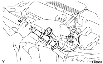
Fill the radiator with coolant and attach a radiator cap tester.
Warm up the engine.
Using a radiator cap tester, increase the pressure inside the radiator to 118 kPa (1.2 kgf*cm, 17 psi), and check that the pressure does not drop.
If the pressure drops, check the hoses, radiator and water pump for leaks. If no external leaks are found, check the heater core, cylinder block and cylinder head.
| 109. CHECK FOR EXHAUST GAS LEAKS |
| 110. INSPECT AND ADJUST FRONT WHEEL ALIGNMENT |
| 111. INSTALL ENGINE UNDER COVER NO.2 |
Install the 2 bolts and engine under cover No.2.
| 112. INSTALL FRONT FENDER APRON SEAL LH |
Install the 2 bolts, clip and fender apron seal LH.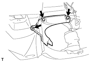
| 113. INSTALL FRONT FENDER APRON SEAL RH |
- HINT:
- Perform the same procedure as above on the opposite side.
| 114. INSTALL FRONT FENDER SPLASH SHIELD SUB-ASSEMBLY LH |
Install the fender splash shield with the screw.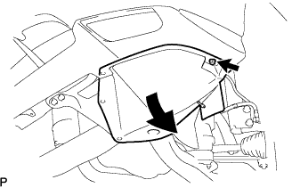
| 115. INSTALL FRONT FENDER SPLASH SHIELD SUB-ASSEMBLY RH |
- HINT:
- Perform the same procedure as above on the opposite side.
| 116. INSTALL ENGINE UNDER COVER NO.1 |
Install the 6 bolts, 2 screws, 2 clips and engine under cover.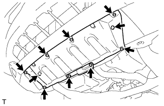
| 117. INSPECT STEERING WHEEL CENTER POINT |
| 118. INSPECT IGNITION TIMING |
Set the vehicle to inspection mode (Click here).
Warm up the engine.
When using the intelligent tester:
Connect the intelligent tester (with CAN VIM) to the DLC3.
Enter DATA LIST MODE on the intelligent tester.
- Ignition timing:
- 8 to 12° BTDC
- NOTICE:
- Turn all the electrical systems off.
- Inspect the engine idle speed with the cooling fan off.
- Turn all the electrical systems off.
- HINT:
- Refer to the intelligent tester operator's manual if you need help to select DATA LIST.
Check that the ignition timing advances immediately when the engine speed is increased.
When not using the intelligent tester: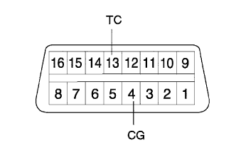
Using SST, connect terminals 13 (TC) and 4 (CG) of the DLC3.
- SST
- 09843-18040
- NOTICE:
- Make sure of the terminal numbers before connecting them. Connection with a wrong terminal can damage the engine.
- Turn off all electrical systems before connecting the terminals.
- Perform this inspection after the cooling fan motor is turned off.
- Make sure of the terminal numbers before connecting them. Connection with a wrong terminal can damage the engine.
Pull out the red-colored wire harness as shown in the illustration.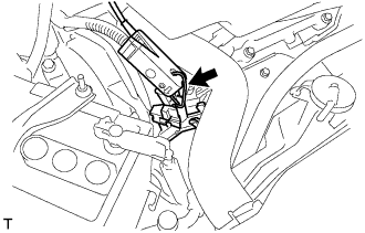
Connect the tester terminal of the timing light to the engine.
- NOTICE:
- Use a timing light which detects the first signal.
Inspect ignition timing at idle.
- Ignition timing:
- 8 to 12° BTDC
- NOTICE:
- When checking the ignition timing, the transmission is in neutral.
- HINT:
- Run the engine at 1,000 to 1,300 rpm for 5 seconds, check that the engine rpm returns to idle speed.
Disconnect terminals 13 (TC) and 4 (CG) of the DLC3.
Inspect ignition timing at idle.
- Ignition timing:
- 7 to 24° BTDC
Confirm that the ignition timing advances when the engine rpm is increased.
Remove the timing light.
| 119. INSPECT ENGINE IDLE SPEED |
Set the vehicle to inspection mode (Click here).
Warm up the engine.
Connect the intelligent tester (with CAN VIM) to the DLC3.
Enter DATA LIST MODE on the intelligent tester.
- Idle speed:
- 850 to 950 rpm.
- NOTICE:
- When checking the idle speed, the transmission is in neutral.
- Check the idle speed with the cooling fan off.
- Switch off all accessories and air conditioning before connecting the intelligent tester.
- When checking the idle speed, the transmission is in neutral.
- HINT:
- Refer to the intelligent tester operator's manual for further details.
| 120. INSPECT CO/HC |
Set the vehicle to inspection mode (Click here).
Start the engine.
Run the engine at 2,500 rpm for approximately 180 seconds.
Insert the CO/HC meter testing probe at least 40 cm (1.3 ft) into the tailpipe during idling.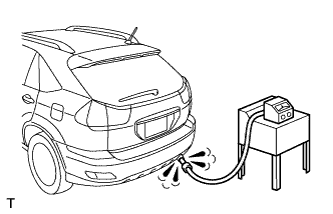
Check CO/HC concentration at idle and/or 2,500 rpm.
- HINT:
- When doing the 2 mode (with the engine is in the idle and 2,500 rpm) test, the measuring procedures are prescribed by the applicable local regulations.
Check heated oxygen sensor operation (Click here).
Check heated air fuel ratio sensor operation (Click here).
See the table below for possible causes, and then inspect and repair the applicable causes if necessary.
CO
HC
Problems
Causes
Normal
High
Rough idle
- Faulty ignitions:
- Incorrect timing
- Fouled, shorted or improperly gapped plugs
- Incorrect valve clearance
- Leaks in intake and exhaust valves
- Leaks in cylinders
Low
High
Rough idle
(Fluctuating HC reading)
- Vacuum leaks:
- PCV hoses
- Intake manifold
- Throttle body
- Brake booster line
- Lean mixture causing misfire
High
High
Rough idle
(Black smoke from exhaust)
- Restricted air filter
- Plugged PCV valve
- Faulty EFI systems:
- Faulty pressure regulator
- Defective water temperature sensor
- Defective mass air-flow meter
- Faulty ECM
- Faulty injectors
- Faulty throttle position sensor
- Faulty ignitions:
| 121. CHECK ABS SPEED SENSOR SIGNAL |
| 122. PERFORM INITIALIZATION |
Some system need initialization when reconnecting the battery cable. (Click here)
| 123. INSTALL ENGINE ROOM COVER SIDE |
Install the 5 clips and engine room cover side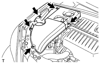
| 124. INSTALL ENGINE ROOM SIDE LH COVER |
Fit the clips and install the engine room side LH cover.