INSTALLATION
Removal / installation
| 1. INSTALL BRAKE ACTUATOR ASSEMBLY |

Install the brake actuator assembly with bracket to the body with the 3 nuts.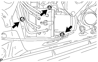

- Torque:
- 19 N*m{ 194 kgf*cm , 14 ft.*lbf }
- NOTICE:
- Do not damage the brake tubes.
Connect the brake actuator connector.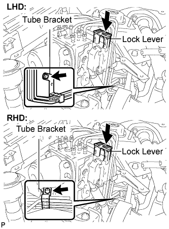
- NOTICE:
- Make sure that the connector is locked securely.
Install the brake tube bracket with the bolt.
- Torque:
- 5.0 N*m{ 51 kgf*cm , 44 in.*lbf }
Using SST, connect the front brake No.8 tube to the front flexible hose.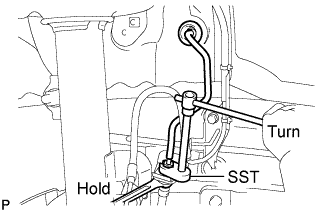
- SST
- 09023-00101
- Torque:
- 15 N*m{ 155 kgf*cm , 11 ft.*lbf }
Using SST, connect each brake tube to the correct positions on top of the actuator assembly with bracket as shown in the illustration.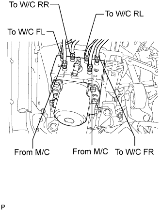
- SST
- 09023-00101
- Torque:
- 15 N*m{ 155 kgf*cm , 11 ft.*lbf }
Install the brake actuator bracket No.7 with clamp with the bolt.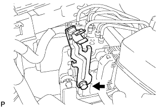
- Torque:
- 19 N*m{ 194 kgf*cm , 14 ft.*lbf }
| 2. INSTALL FRONT WHEEL RH |
- Torque:
- 103 N*m{ 1,050 kgf*cm , 76 ft.*lbf }
| 3. INSTALL BRAKE MASTER CYLINDER RESERVOIR ASSEMBLY |
Install the brake master cylinder reservoir assembly with the 2 bolts.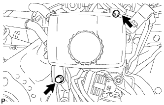
- Torque:
- 9.0 N*m{ 92 kgf*cm , 80 in.*lbf }
Install the 2 reservoir tubes with the 2 clips.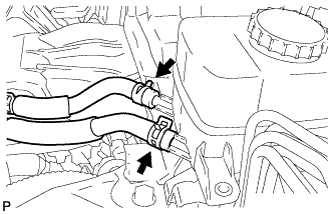
Install the brake actuator hose with the 2 clips.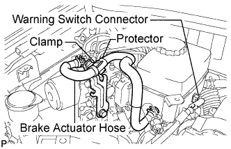
Install the brake actuator hose to the clamp.
- NOTICE:
- Install the brake actuator hose with the edges of the protector and clamp aligned.
Connect the warning switch connector.
| 4. INSTALL COWL PANEL SUB-ASSEMBLY |
Remove the 4 shock absorber nuts.
Install the 4 bolts, 2 nuts and cowl top panel sub-assembly.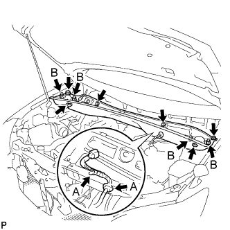
- Torque:
- 5.0 N*m{ 51 kgf*cm , 44 in.*lbf }
Install the 4 shock absorber nuts (B).
- Torque:
- 80 N*m{ 815 kgf*cm , 59 ft.*lbf }
Install the wire harness clamp and grommet (A).
| 5. INSTALL WIND SHIELD WIPER MOTOR ASSEMBLY |
Install the windshield wiper motor and link assembly with the 5 bolts.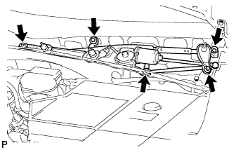
- Torque:
- 7.0 N*m{ 71 kgf*cm , 62 in.*lbf }
Connect the connector.
| 6. INSTALL COWL TOP VENTILATOR LOUVER SUB-ASSEMBLY |
Remove the 4 shock absorber nuts.
Install the 4 bolts, 2 nuts and cowl top panel sub-assembly.
- Torque:
- 5.0 N*m{ 51 kgf*cm , 44 in.*lbf }
Install the 4 shock absorber nuts (B).
- Torque:
- 80 N*m{ 815 kgf*cm , 59 ft.*lbf }
Install the wire harness clamp and grommet (A).
| 7. INSTALL FRONT WIPER ARM AND BLADE ASSEMBLY RH |
Clean the wiper arm serrations.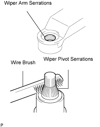
Clean the wiper pivot serrations with a wire brush (when reinstalling).
Install the front wiper arm and blade assembly RH with the 2 nuts at the position as shown in the illustration.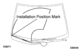
- Torque:
- 24 N*m{ 245 kgf*cm , 18 ft.*lbf }
- HINT:
- Hold the arm hinge by hand to fasten the nut.
Operate the front wipers while spraying water or washer fluid on the windshield.
Make sure that the wipers function properly and there is no interference with the vehicle body.
| 8. INSTALL FRONT WIPER ARM AND BLADE ASSEMBLY LH |
Operate the front wiper, and stop the front wiper motor at the automatic stop position.
Clean the wiper arm serrations.
Clean the wiper pivot serrations with a wire brush (when reinstalling).
Install the front wiper arm and blade assembly LH with the nut at the position as shown in the illustration.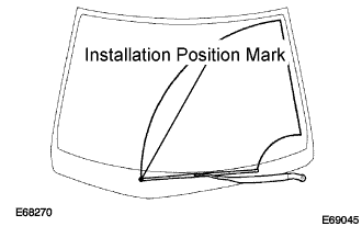
- Torque:
- 24 N*m{ 245 kgf*cm , 18 ft.*lbf }
- HINT:
- Hold the arm hinge by hand to fasten the nut.
| 9. INSTALL FRONT FENDER TO COWL SIDE SEAL LH |
| 10. INSTALL FRONT FENDER TO COWL SIDE SEAL RH |
| 11. FILL RESERVOIR WITH BRAKE FLUID |
Add brake fluid to the MAX line in the reservoir.
- Fluid:
- SAE J1703 or FMVSS No. 116 DOT3
- CAUTION:
- Add brake fluid carefully and check that the reservoir level remains between the MIN and MAX lines while bleeding the brakes.
- Do not stand the fluid can on the reservoir inlet when bleeding the brake actuator. Doing so will cause brake fluid to overflow.
- Add brake fluid carefully and check that the reservoir level remains between the MIN and MAX lines while bleeding the brakes.
| 12. BLEED BRAKE ACTUATOR HOSE |
Connect SST to the reservoir with the brake reservoir pressure adapter.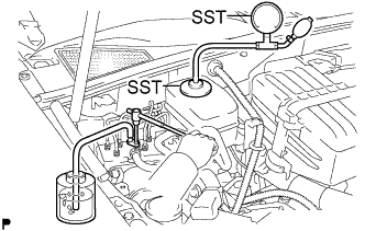
- SST
- 09992-00242
09992-00350
Using SST, loosen the bleeder plug of the actuator.
- SST
- 09023-00101
Connect a vinyl tube to the bleeder plug of the actuator.
Use the SST to boost pressure in the reservoir.
- Standard:
- 50 to 80 kPa (0.5 to 0.8 kgf/cm2, 7.3 to 11.6 psi)
Drain approximately 100 cc of fluid.
Tighten the bleeder plug and boost the pressure in the reservoir again (50 to 80 kPa (0.5 to 0.8 kgf/cm2)). Then, loosen the bleeder plug and bleed the brake actuator hose.
- NOTICE:
- Repeat this procedure at least 5 times.
When air is completely bled out from the hose between the reservoir and the actuator, tighten the bleeder plug.
- Torque:
- 8.3 N*m{ 85 kgf*cm , 74 in.*lbf }
| 13. BLEED FRONT BRAKE SYSTEM |
- HINT:
- Air can be easily bled from the front brake system if air has been bled from the master cylinder when replacing the brake master cylinder assembly.
- NOTICE:
- If brake fluid leaks onto any painted surface of the vehicle, wash or otherwise remove it completely.
- Bleed the air by following the steps displayed on the intelligent tester.
- If brake fluid leaks onto any painted surface of the vehicle, wash or otherwise remove it completely.
Depress the brake pedal several times and bleed the front brake system from the bleeder plugs on the front brake cylinder RH and LH.
- HINT:
- Repeat the procedure until air is completely bled from the front brake system.
Tighten the bleeder plugs after bleeding.
- Torque:
- 8.3 N*m{ 85 kgf*cm , 74 in.*lbf }
| 14. INSTALL ABS MOTOR RELAY |
Install the 2 ABS motor relays.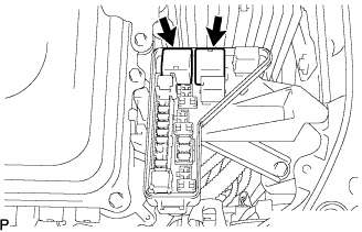
| 15. CLEAR DTC |
| 16. BLEED REAR BRAKE SYSTEM |
- CAUTION:
- Never bleed air from the brake hydraulic system without using the intelligent tester. Failure to use the intelligent tester could cause serious injury or an accident.
- NOTICE:
- Bleed the air by following the steps displayed on the intelligent tester.
Connect the intelligent tester to the DLC3 with the ignition switch off.
Check that the parking brake is applied and turn the ignition switch to the ON position.
Turn on the intelligent tester and select "DIAGNOSTIC MENU"→"ABS/VSC"→"ECB UTILITY"→"ECB INVALID".
With the brake pedal depressed, bleed the rear brake system from the bleeder plug on the rear disc brake cylinder LH while the pump motor and solenoid are operating.
- CAUTION:
- Keep the fluid inside the reservoir above the LOW level by replenishing.
- HINT:
- Depress and hold the brake pedal.
- After the solenoid operates for approximately 30 seconds, release the brake pedal to stop the solenoid.
- Repeat the procedures until air is completely bled from the rear brake system.
- The ECB warning light comes on and the buzzer sounds while bleeding, but they do not indicate a malfunction.
- Depress and hold the brake pedal.
Tighten the bleeder plug after bleeding.
- Torque:
- 8.3 N*m{ 85 kgf*cm , 74 in.*lbf }
Turn the intelligent tester on and select "DIAGNOSTIC MENU"→"ABS/VSC"→"ECB UTILITY"→"ECB INVALID"
With the brake pedal depressed, bleed the rear brake system from the bleeder plug on the rear disc brake cylinder RH while the pump motor and solenoid are operating.
- CAUTION:
- Keep the fluid inside the reservoir above the LOW level by replenishing.
- HINT:
- Depress and hold the brake pedal.
- After the solenoid operates for approximately 30 seconds, release the brake pedal to stop the solenoid
- Repeat the procedures until air is completely bled from the rear brake system.
- The ECB warning light comes on and the buzzer sounds while bleeding, but they do not indicate a malfunction.
- Depress and hold the brake pedal.
Tighten the bleeder plug after bleeding.
- Torque:
- 8.3 N*m{ 85 kgf*cm , 74 in.*lbf }
| 17. PERFORM ACCUMULATOR ZERO DOWN |
- CAUTION:
- Never bleed air from the brake hydraulic system without using the intelligent tester. Failure to use the intelligent tester could cause serious injury or an accident.
- Be sure to perform this procedure before replacement, removal, or installation of the actuator.
- Never bleed air from the brake hydraulic system without using the intelligent tester. Failure to use the intelligent tester could cause serious injury or an accident.
- NOTICE:
- Perform accumulator zero down by following the steps displayed on the intelligent tester.
Connect the intelligent tester to the DLC3 with the ignition switch off
Depressurize the accumulator.
Check that the parking brake is applied and turn the ignition switch to the ON position.
Turn on the intelligent tester and select "DIAGNOSTIC MENU" → "ABS/VSC" → "ECB UTILITY" → "ZERO DOWN" on the intelligent tester.
When the buzzer sounds, turn the ignition switch off.
Circulate the fluid in the accumulator.
Depressurize the accumulator 5 times.
- HINT:
- Accumulator pressure is released and accumulated repeatedly, which circulates the fluid inside the accumulator, when repeating accumulator zero down.
- The pump motor rotates and the accumulator is pressurized every time the ignition switch is turned from off to on.
- Accumulator pressure is released and accumulated repeatedly, which circulates the fluid inside the accumulator, when repeating accumulator zero down.
| 18. CHECK BRAKE FLUID LEVEL |
After performing accumulator zero down (accumulator depressurizing), return the fluid in the accumulator back to the reservoir and then adjust the fluid level in the master cylinder reservoir to the MAX level.
- HINT:
- After performing accumulator zero down (accumulator depressurizing), fluid is built up in the accumulator by turning the ignition switch to the ON position and the fluid level of the reservoir lowers.
- If the fluid level is adjusted without performing accumulator zero down (accumulator depressurizing), fluid is sent from the accumulator to the reservoir. The fluid level may exceed the MAX level, but it is normal.
- After performing accumulator zero down (accumulator depressurizing), fluid is built up in the accumulator by turning the ignition switch to the ON position and the fluid level of the reservoir lowers.
| 19. CHECK AND CLEAR DTC |
| 20. PERFORM LINEAR VALVE OFFSET LEARNING |
| 21. CHECK FOR BRAKE FLUID LEAKAGE |