DISASSEMBLY
Removal / installation
| 1. REMOVE REAR WIPER ARM COVER |

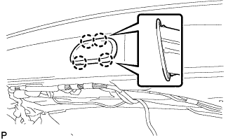
Remove rear wiper arm cover.
| 2. REMOVE REAR WIPER ARM AND BLADE ASSEMBLY |
Remove the nut, rear wiper arm and blade assembly.
| 3. REMOVE REAR WIPER SHAFT COVER |
Remove the rear wiper shaft cover.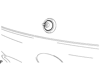

| 4. REMOVE REAR NO.1 WIPER LINK PIVOT NUT |
Using the socket wrench 27 mm (1.06 in.), remove the rear No.1 wiper link pivot nut.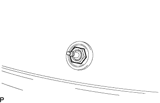
| 5. REMOVE REAR NO.1 WIPER LINK PIVOT WASHER |
Remove the rear No.1 wiper link pivot washer.
| 6. REMOVE BACK WINDOW PANEL TRIM UPPER (w/o Power Back Door) |
Disengage the 2 claws and the 7 clips, and remove the back window panel trim upper.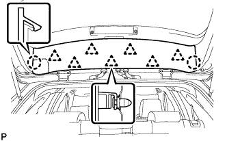
| 7. REMOVE BACK DOOR TRIM BOARD (w/ Power Back Door) |
Disengage the 3 claws and remove the back door trim board.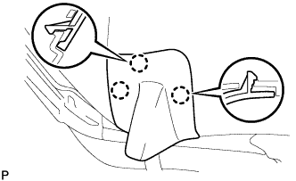
| 8. REMOVE BACK WINDOW PANEL TRIM UPPER (w/ Power Back Door) |
Disengage the 2 claws and the 7 clips, and remove the back window panel trim upper.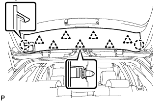
| 9. REMOVE BACK DOOR TRIM PANEL ASSEMBLY UPPER |
Disengage the 10 clips and remove the back door trim panel assembly upper.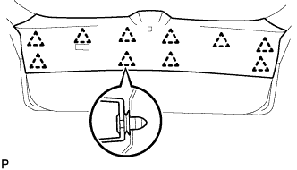
| 10. REMOVE BACK DOOR TRIM PANEL ASSEMBLY |
Disengage the 8 clips and remove the back door trim panel assembly.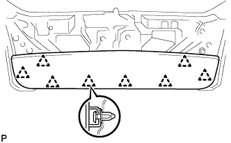
| 11. REMOVE REAR WIPER MOTOR ASSEMBLY |
Disconnect the connector.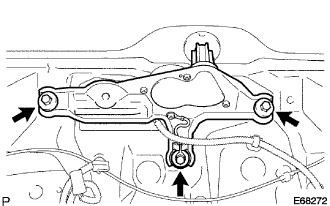
Remove the 3 bolts and the rear wiper motor.
| 12. REMOVE BACK-UP LIGHT ASSEMBLY RH |
Disconnect each connector.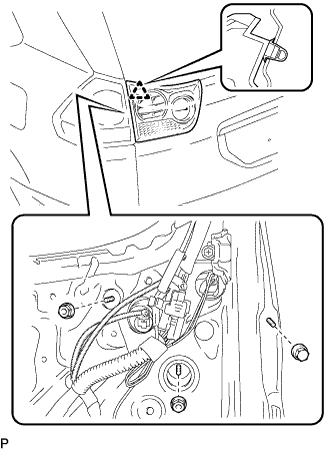
Remove the 3 nuts and disengage the clip, and remove the back-up light assembly.
| 13. REMOVE BACK-UP LIGHT ASSEMBLY LH |
Disconnect each connector.
Remove the 3 nuts and disengage the clip, and remove the back-up light assembly.
| 14. REMOVE BACK DOOR TRIM COVER RH |
Disengage the 3 clips and remove the back door trim cover RH.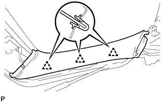
- HINT:
- If a clip remains on the door, remove the clip from the body and install it to the back door trim cover RH.
| 15. REMOVE BACK DOOR TRIM COVER LH |
Disengage the 3 clips and remove the back door trim cover LH.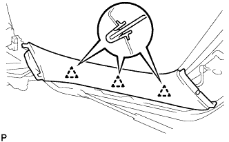
- HINT:
- If a clip remains on the door, remove the clip from the body and install it to the back door trim cover LH.
| 16. REMOVE REAR SPOILER SUB-ASSEMBLY |
Disconnect the center stop light connector.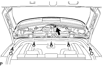
Remove the 2 grommets and 5 bolts.
Remove the 3 clips and rear spoiler sub-assembly.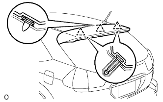
| 17. REMOVE BACK DOOR TRIM SPACER (RH Side) |
Remove the screw.
Disengage the clip and remove the back door trim spacer.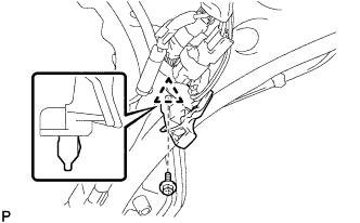
| 18. REMOVE BACK DOOR TRIM SPACER (LH Side) |
Remove the screw.
Disengage the clip and remove the back door trim spacer.
| 19. REMOVE BACK DOOR LOCK COVER |
Disengage the 4 claws and remove the back door lock cover.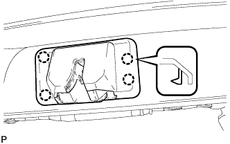
| 20. REMOVE BACK DOOR LOCK ASSEMBLY (w/o Power Back Door) |
Separate the link rod as shown in the illustration.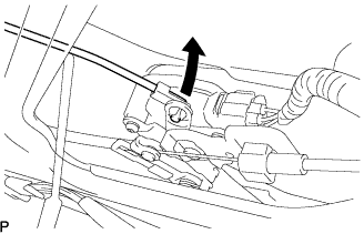
Disconnect the connector and remove the clamp.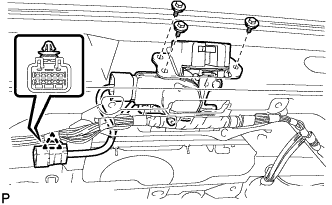
Remove the 3 bolts and the back door lock assembly.
| 21. REMOVE BACK DOOR LOCK ASSEMBLY (w/ Power Back Door) |
Separate the link rod as shown in the illustration.
Disconnect each connector and remove the clamp.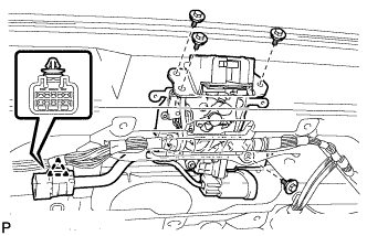
Remove the 4 bolts and the back door lock assembly.
| 22. REMOVE POWER BACK DOOR SENSOR ASSEMBLY RH (w/ Power Back Door) |
Disconnect the connector.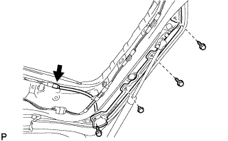
Remove the clip.
Using a "torx" socket wrench (T30), remove the 3 screws and the power back door sensor assembly RH.
| 23. REMOVE POWER BACK DOOR SENSOR ASSEMBLY LH (w/ Power Back Door) |
Disconnect the connector.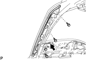
Remove the clip.
Using a "torx" socket wrench (T30), remove the 3 screws and the power back door sensor assembly LH.
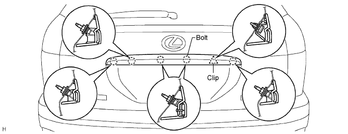
| 24. REMOVE BACK DOOR GARNISH |
Disengage the back door opener switch connector.
Remove the 5 bolts, clip and garnish.
| 25. REMOVE BACK DOOR OPENER SWITCH ASSEMBLY |
Remove the 2 screws.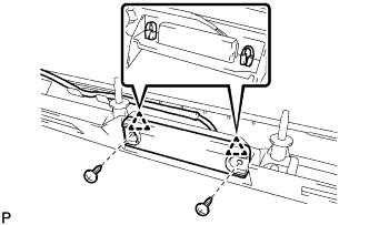
Disengage the 2 clamps and remove the back door opener switch assembly.
| 26. REMOVE TELEVISION CAMERA (w/ Back Guide Monitor System) |
Disconnect the connector and disengage the clamp.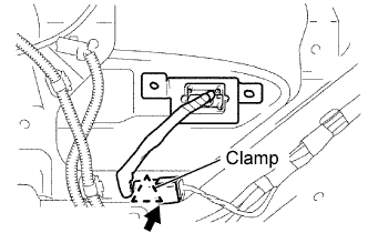
Disengage the 2 claws and remove the television camera.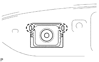
| 27. REMOVE LICENSE PLATE LIGHT ASSEMBLY |
Disengage the 2 claws and separate the license plate light assembly as shown in the illustration.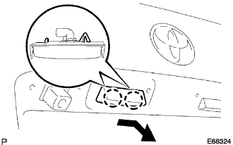
Disconnect the connector and remove the license plate light assembly.
| 28. REMOVE POWER BACK DOOR WARNING BUZZER (w/ Power Back Door) |
Disconnect the connector.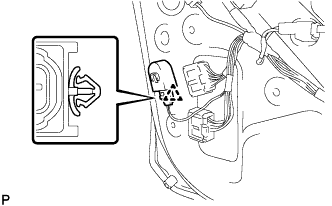
Remove the clamp and power back door warning buzzer.
| 29. REMOVE POWER BACK DOOR CONTROL SWITCH ASSEMBLY (w/ Power Back Door) |
Remove the clamp and disconnect the connector.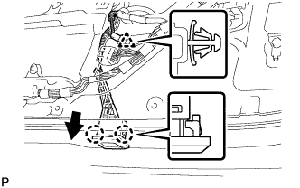
Disengage the 2 claws and remove the power back door control switch assembly as shown in the illustration.
| 30. REMOVE DOOR PULL HANDLE |
Disengage the 4 claws and remove the door pull handle.