B2415 Malfunction of skid control ECU Open or short of vehicle speed sensor circuit
Diagnostic trouble codes
DESCRIPTION
The AFS ECU receives the vehicle speed signal of the rear wheels from the skid control ECU.| DTC No. |
DTC Detecting Condition |
Trouble Area |
| B2415 |
|
|
WIRING DIAGRAM
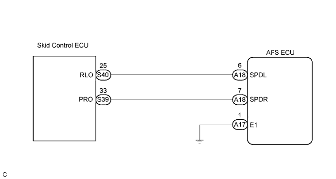

INSPECTION PROCEDURE
| 1. CHECK DTC (ELECTRONICALLY CONTROLLED BRAKE SYSTEM) |

Check the DTC of electronically controlled brake system (Click here).
- OK:
- DTC is not output.
|
|
||||

| OK | |
 |
| 2. CHECK HARNESS AND CONNECTOR (SKID CONTROL ECU - AFS ECU) |
Disconnect the skid control ECU connector and AFS ECU connector.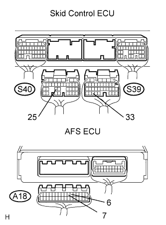
Measure the resistance according to the value(s) in the table below.
- Resistance:
Tester connection
Condition
Specified condition
PRO (S39-33) - SPDR (A18-7)
Always
Below 1 Ω
RLO (S40-25) - SPDL (A18-6)
Always
Below 1 Ω
SPDR (A18-7) - Body ground
Always
10 kΩ or higher
SPDL (A18-6) - Body ground
Always
10 kΩ or higher
|
|
||||
| OK | |
|
| 3. INSPECT AFS ECU |
Measure the voltage according to the value(s) in the table below.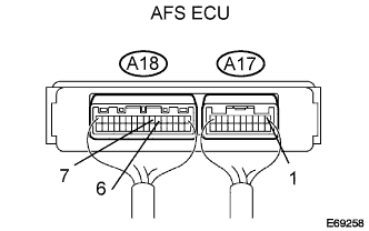
- Voltage:
Tester connection
Condition
Specified condition
SPDL (A18-6) - E1 (A17-1)
Drive at about 30 km/h (19 mph)
0 to 14 V
Pulse generation(*1)
SPDR (A18-7) - E1 (A17-1)
Drive at about 30 km/h (19 mph)
0 to 14 V
Pulse generation (*1)
*1: Oscilloscope wave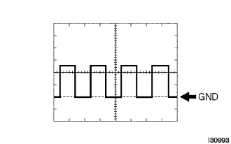
- HINT:
- Gauge set: 5 V/DIV, 2 ms/DIV
- Condition: Drive at about 30 km/h (19 mph)
- Gauge set: 5 V/DIV, 2 ms/DIV
- Result:
Condition
Proceed to
OK (When checking from the DTC)
A
OK (When checking from the PROBLEM SYMPTOMS TABLE)
B
NG
C
|
|
||||
|
|
||||
| A | ||
 |
||
| ||