B2416 Open or short in height control sensor rear RH circuit
Diagnostic trouble codes
DESCRIPTION
The AFS ECU receives the signals from the height control sensor rear RH.| DTC No. |
DTC Detecting Condition |
Trouble Area |
| B2416 |
|
|
WIRING DIAGRAM
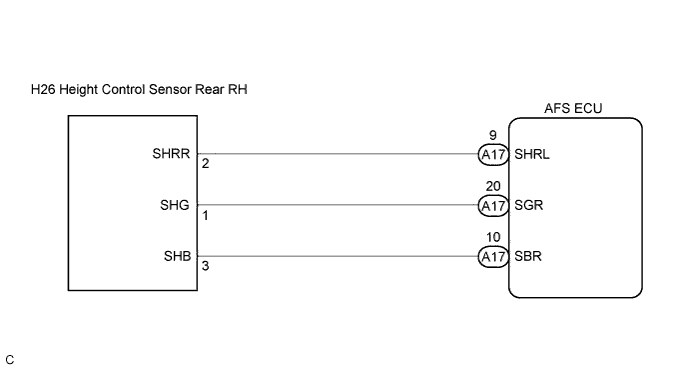

INSPECTION PROCEDURE
| 1. CHECK HARNESS AND CONNECTOR (HEIGHT CONTROL SENSOR SUB-ASSEMBLY REAR RH POWER SOURCE) |

Disconnect the H26 connector from the height control sensor rear RH.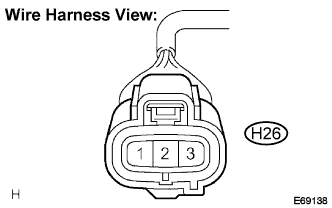
Measure the voltage according to the value(s) in the table below.
- Voltage:
Tester connection
Condition
Specified condition
SHB (H26-3) - SHG (H26-1)
Ignition switch ON
4.5 to 5.5 V
|
|
||||

| OK | |
 |
| 2. INSPECT HEIGHT CONTROL SENSOR SUB-ASSEMBLY REAR RH |
Connect 3 dry cell batteries (1.5 V) in a series.
Connect the positive (+) lead from the battery to terminal 1 and the negative (-) lead from the battery to terminal 3.
Measure the voltage between terminal 2 and terminal 3 when slowly moving the link up and down.
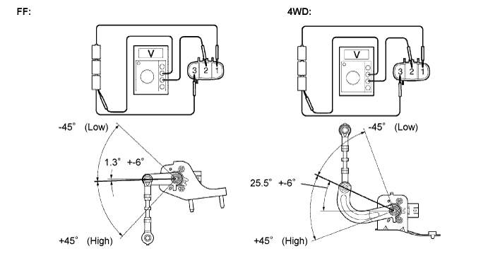
- Voltage:
Link Angle
Standard voltage
+45°(High)
4.5 V
0°(Normal)
2.5 V
-45°(Low)
0.5 V
|
|
||||

| OK | |
|
| 3. CHECK HARNESS AND CONNECTOR (AFS ECU - HEIGHT CONTROL SENSOR REAR RH) |
Disconnect the A17 connector from the AFS ECU.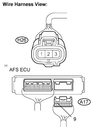
Disconnect the H26 connector from the height control sensor sub-assembly rear RH.
Measure the resistance according to the value(s) in the following table.
- Resistance:
Tester connection
Condition
Specified condition
SHRL (A17-9) - SHRR (H26-2)
Always
Below 1 Ω
SHRL (A17-9) - Body ground
Always
10 kΩ or higher
- Result:
Condition
Proceed to
OK (When checking from the DTC)
A
OK (When checking from the PROBLEM SYMPTOMS TABLE)
B
NG
C
|
|
||||
|
|
||||
| A | ||
 |
||
| ||
| 4. INSPECT AFS ECU |
Measure the voltage according to the value(s) in the table below.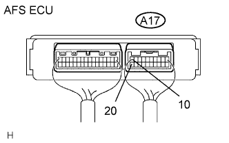
- Voltage:
Tester connection
Condition
Specified condition
SBR (A17-10) - SGR (A17-20)
Ignition switch ON
4.5 to 5.5 V
- Result:
Condition
Proceed to
OK
A
NG (When checking from the DTC)
B
NG (When checking from the PROBLEM SYMPTOMS TABLE)
C
|
|
||||
|
|
||||
| A | ||
|
||
| ||