B2417 Malfunction of headlight beam level control motor LH Open or short of headlight beam level control motor LH...
Diagnostic trouble codes
DESCRIPTION
The leveling actuator receives the signal from the AFS ECU to operate. The AFS ECU receives the signal regarding the operating conditions of the leveling actuator.| DTC No. |
DTC Detecting Condition |
Trouble Area |
| B2417 |
|
|
| B2418 |
|
|
WIRING DIAGRAM
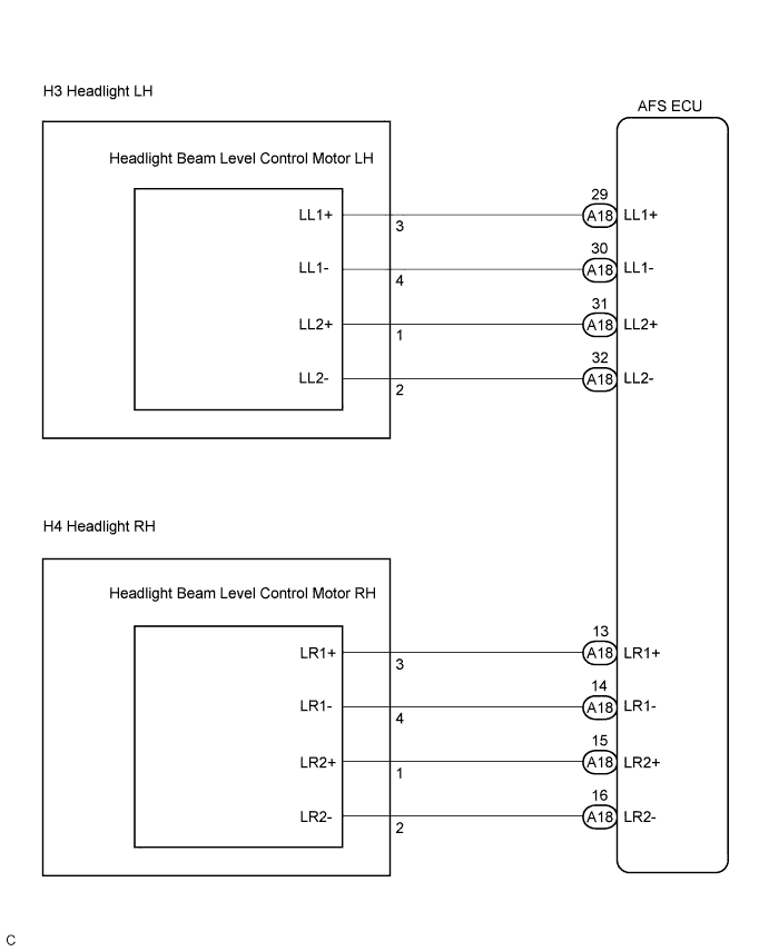

INSPECTION PROCEDURE
| 1. CHECK HARNESS AND CONNECTOR (HEADLIGHT BEAM LEVEL CONTROL MOTOR - AFS ECU) |

Disconnect the headlight connector of headlight beam level control motor side and AFS ECU connector.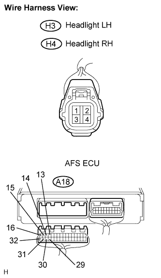
Measure the resistance according to the value(s) in the table below.
- Resistance:
- LH Side (B2417):
Tester connection
Condition
Specified condition
LL2+ (H3-1) - LL2+ (A18-31)
Always
Below 1 Ω
LL2- (H3-2) - LL2- (A18-32)
Always
Below 1 Ω
LL1+ (H3-3) - LL1+ (A18-29)
Always
Below 1 Ω
LL1- (H3-4) - LL1- (A18-30)
Always
Below 1 Ω
LL1+ (A18-29) - Body ground
Always
10 kΩ or higher
LL1- (A18-30) - Body ground
Always
10 kΩ or higher
LL2+ (A18-31) - Body ground
Always
10 kΩ or higher
LL2- (A18-32) - Body ground
Always
10 kΩ or higher
- LH Side (B2418):
Tester connection
Condition
Specified condition
LR2+ (H4-1) - LR2+ (A18-15)
Always
Below 1 Ω
LR2- (H4-2) - LR2- (A18-16)
Always
Below 1 Ω
LR1+ (H4-3) - LR1+ (A18-13)
Always
Below 1 Ω
LR1- (H4-4) - LR1- (A18-14)
Always
Below 1 Ω
LR1+ (A18-13) - Body ground
Always
10 kΩ or higher
LR1- (A18-14) - Body ground
Always
10 kΩ or higher
LR2+ (A18-15) - Body ground
Always
10 kΩ or higher
LR2- (A18-16) - Body ground
Always
10 kΩ or higher
|
|
||||

| OK | |
 |
| 2. INSPECT HEADLIGHT BEAM LEVEL CONTROL MOTOR |
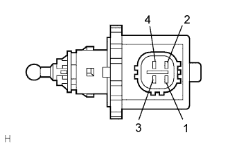 |
Disconnect the headlight connector of headlight beam level control motor side.
Measure the resistance according to the value(s) in the table below.
- Resistance:
- LH Side (B2417):
Tester connection
Condition
Specified condition
LL2+ (1) - LL2- (2)
Always
5.8 to 12.5 Ω
LL1+ (3) - LL1- (4)
Always
5.8 to 12.5 Ω
- RH Side (B2418):
Tester connection
Condition
Specified condition
LR2+ (1) - LR2- (2)
Always
5.8 to 12.5 Ω
LR1+ (3) - LR1- (4)
Always
5.8 to 12.5 Ω
- Result:
Condition
Proceed to
OK (When checking from the DTC)
A
OK (When checking from the PROBLEM SYMPTOMS TABLE)
B
NG
C
|
|
||||
|
|
||||
| A | ||
 |
||
| ||