Headlight Beam Level Control Actuator Circuit
Circuit diagnosis
DESCRIPTION
When the actuator is received a signal from the headlight beam level control ECU, the step motor is activated and the angle of the reflector in the headlight will be adjusted.WIRING DIAGRAM
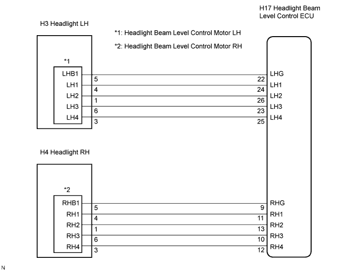

INSPECTION PROCEDURE
| 1. INSPECT HEADLIGHT BEAM LEVEL CONTROL MOTOR LH |

Disconnect the connector from headlight beam level control motor LH.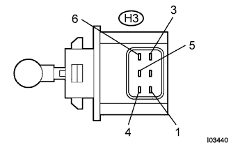
Measure the resistance according to the value(s) in the table below.
- Resistance:
Tester connection
Condition
Specified condition
1 (LH2) - 5 (LHB1)
Always
26 to 30 Ω
3 (LH4) - 5 (LHB1)
Always
26 to 30 Ω
4 (LH1) - 5 (LHB1)
Always
26 to 30 Ω
6 (LH3) - 5 (LHB1)
Always
26 to 30 Ω
|
|
||||

| OK | |
 |
| 2. CHECK HARNESS AND CONNECTOR (LEVEL CONTROL MOTOR LH - LEVEL CONTROL ECU) |
Disconnect the H3 connector of headlight beam level control motor LH and the H17 connector of the headlight beam level control ECU.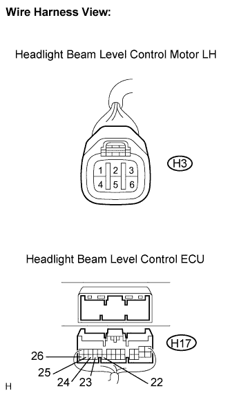
Measure the resistance according to the value(s) in the table below.
- Resistance:
Tester connection
Condition
Specified condition
H3-1 (LH2) - H17-26 (LH2)
Always
Below 1 Ω
H3-3 (LH4) - H17-25 (LH4)
Always
Below 1 Ω
H3-4 (LH1) - H17-24 (LH1)
Always
Below 1 Ω
H3-5 (LHB1) - H17-22 (LHG)
Always
Below 1 Ω
H3-6 (LH3) - H17-23 (LH3)
Always
Below 1 Ω
H17-26 (LH2) - Body ground
Always
10 kΩ or higher
H17-25 (LH4) - Body ground
Always
10 kΩ or higher
H17-24 (LH1) - Body ground
Always
10 kΩ or higher
H17-22 (LHG) - Body ground
Always
10 kΩ or higher
H17-23 (LH3) - Body ground
Always
10 kΩ or higher
|
|
||||
| OK | |
|
| 3. INSPECT HEADLIGHT BEAM LEVEL CONTROL MOTOR RH |
Disconnect the connector from headlight leveling motor RH.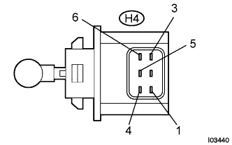
Measure the resistance according to the value(s) in the table below.
- Resistance:
Tester connection
Condition
Specified condition
1 (RH2) - 5 (RHB1)
Always
26 to 30 Ω
3 (RH4) - 5 (RHB1)
Always
26 to 30 Ω
4 (RH1) - 5 (RHB1)
Always
26 to 30 Ω
6 (RH3) - 5 (RHB1)
Always
26 to 30 Ω
|
|
||||
| OK | |
|
| 4. CHECK HARNESS AND CONNECTOR (LEVEL CONTROL MOTOR RH - LEVEL CONTROL ECU) |
Disconnect the H4 connector of headlight beam level control motor RH and the H17 connector of the headlight beam level control ECU.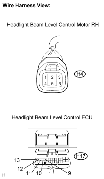
Measure the resistance according to the value(s) in the table below.
- Resistance:
Tester connection
Condition
Specified condition
H4-1 (RH2) - H17-13 (RH2)
Always
Below 1 Ω
H4-3 (RH4) - H17-12 (RH4)
Always
Below 1 Ω
H4-4 (RH1) - H17-11 (RH1)
Always
Below 1 Ω
H4-5 (RHB1) - H17-9 (RHG)
Always
Below 1 Ω
H4-6 (RH3) - H17-10 (RH3)
Always
Below 1 Ω
H17-13 (RH2) - Body ground
Always
10 kΩ or higher
H17-12 (RH4) - Body ground
Always
10 kΩ or higher
H17-11 (RH1) - Body ground
Always
10 kΩ or higher
H17-9 (RHG) - Body ground
Always
10 kΩ or higher
H17-10 (RH3) - Body ground
Always
10 kΩ or higher
|
|
||||
| OK | ||
 |
||
| ||