C1568 DC-DC converter malfunction
Diagnostic trouble codes
DESCRIPTION
The power steering converter is activated and stopped by the power steering ECU assembly.This converter reduces the voltage supplied from the hybrid vehicle battery to 42 V and outputs the voltage as a power source for the power steering motor.
| DTC No. |
DTC Detection Condition |
Trouble Area |
| C1568 |
DC-DC converter malfunction |
|
WIRING DIAGRAM
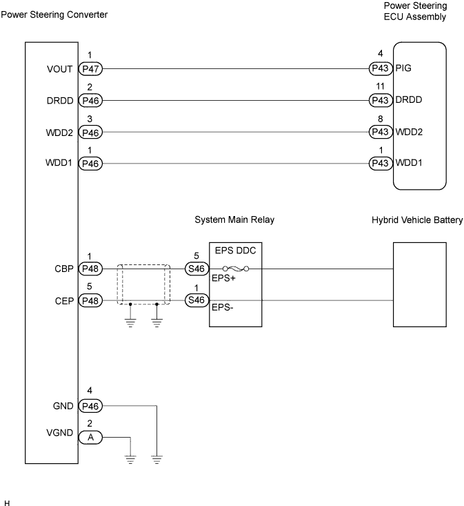

INSPECTION PROCEDURE
- CAUTION:
- Before inspecting the high-voltage system, take safety precautions to prevent electrical shocks, such as wearing insulated gloves and removing the service plug grip. After removing the service plug grip, put it in your pocket to prevent other technicians from reconnecting it while you are working on the high-voltage system.
- After disconnecting the service plug grip, wait for at least 5 minutes before touching any of the high-voltage connectors or terminals.
- Wear insulated gloves, turn the ignition switch off, and disconnect the negative terminal of the auxiliary battery before touching any of the orange-colored wires of the high-voltage system.
- Before inspecting the high-voltage system, take safety precautions to prevent electrical shocks, such as wearing insulated gloves and removing the service plug grip. After removing the service plug grip, put it in your pocket to prevent other technicians from reconnecting it while you are working on the high-voltage system.
- NOTICE:
- After removing the service plug grip, do not put the vehicle into the READY-on state, unless instructed by the repair manual.
- Turn the ignition switch off before disconnecting or reconnecting any connector.
- After removing the service plug grip, do not put the vehicle into the READY-on state, unless instructed by the repair manual.
| 1. CHECK OTHER DTC OUTPUT (HYBRID CONTROL SYSTEM) |

Check for DTCs of the hybrid control system (Click here).
- OK:
- DTCs of the hybrid control system are not output.
|
|
||||

| OK | |
 |
| 2. CHECK HARNESS AND CONNECTOR (BETWEEN POWER STEERING ECU AND POWER STEERING CONVERTER) |
Disconnect the P46 and P47 connectors from the power steering converter.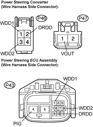
Disconnect the P43 connector from the power steering ECU assembly.
Measure the resistance according to the value(s) in the table below.
- Resistance:
Tester connection (Symbols)
Condition
Specified condition
P47-1 (VOUT) - P43-4 (PIG)
Always
Below 1 Ω
P46-2 (DRDD) - P43-11 (DRDD)
Always
Below 1 Ω
P46-1 (WDD1) - P43-1 (WDD1)
Always
Below 1 Ω
P46-3 (WDD2) - P43-8 (WDD2)
Always
Below 1 Ω
P47-1 (VOUT) - Body ground
Always
10 kΩ or higher
P46-2 (DRDD) - Body ground
Always
10 kΩ or higher
P46-1 (WDD1) - Body ground
Always
10 kΩ or higher
P46-3 (WDD2) - Body ground
Always
10 kΩ or higher
Measure the voltage according to the value(s) in the table below.
- Voltage:
Tester connection (Symbols)
Condition
Specified condition
P47-1 (VOUT) - Body ground
IG switch on
Below 1 V
P46-2 (DRDD) - Body ground
IG switch on
Below 1 V
P46-1 (WDD1) - Body ground
IG switch on
Below 1 V
P46-3 (WDD2) - Body ground
IG switch on
Below 1 V
|
|
||||
| OK | |
|
| 3. CHECK HARNESS AND CONNECTOR (BETWEEN POWER STEERING ECU AND BODY GROUND) |
Check if the earth cable is securely installed to the vehicle body.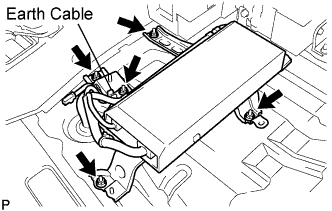
- OK:
- The earth cable is securely installed to the vehicle body.
- HINT:
- Refer to page xx-xx for tightening torque during installation.
Check if the power steering converter is securely installed to the vehicle body.
- OK:
- The converter is securely installed to the vehicle body.
- HINT:
- Refer to page xx-xx for tightening torque during installation.
Disconnect the P46 and A connectors from the power steering converter.
Measure the resistance according to the value(s) in the table below.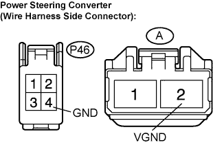
- Resistance:
Tester connection (Symbols)
Condition
Specified condition
P46-4 (GND) - Body ground
Always
Below 1 Ω
A-2 (VGND) - Body ground
Always
Below 1 Ω
|
|
||||
| OK | |
|
| 4. INSPECT SYSTEM MAIN RELAY (EPS DDC FUSE) |
Measure the resistance between terminal 5 (EPS+) of the system main relay connector and the stud bolt shown in the illustration to check the internal EPS DDC fuse.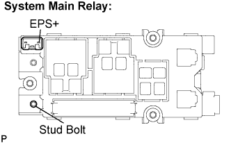
- Resistance:
- Below 1 Ω
- HINT:
- The fuse cannot be replaced. If the resistance is not within the specified range, replace the system main relay.
|
|
||||
| OK | |
|
| 5. CHECK HARNESS AND CONNECTOR (POWER STEERING CONVERTER TO SYSTEM MAIN RELAY) |
Disconnect the P48 connector from the power steering converter.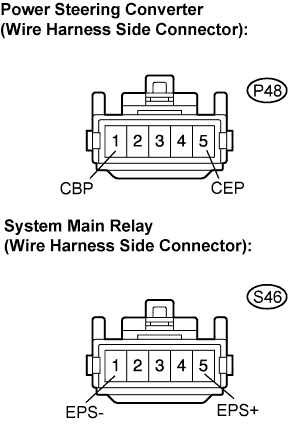
Disconnect the S46 connector from the system main relay.
Measure the resistance according to the value(s) in the table below.
- Resistance:
Tester connection (Symbols)
Condition
Specified condition
P48-1 (CBP) - S46-5 (EPS+)
Always
Below 1 Ω
P48-5 (CEP) - S46-1 (EPS-)
Always
Below 1 Ω
|
|
||||
| OK | |
|
| 6. CHECK POWER STEERING CONVERTER |
Turn the ignition switch off.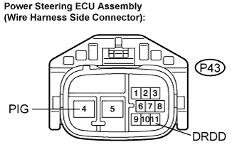
Disconnect the P43 connector from the power steering ECU assembly.
Connect the positive battery terminal to terminal P43-11 (DRDD) of the wire harness side connector of the power steering ECU assembly.
- HINT:
- Apply battery voltage via a 5 A fuse to prevent excess current from flowing into the power steering converter.
Measure the voltage according to the value in the table below.
- Voltage:
Tester connection (Symbols)
Condition
Specified condition
P43-4 (PIG) - Body ground
READY ON
42 to 45 V
- NOTICE:
- If replacing the power steering ECU assembly, initialize the rotation angle sensor value and calibrate the torque sensor zero point (Click here).
|
|
||||
| OK | ||
 |
||
| ||