DISASSEMBLY
Removal / installation
| 1. REMOVE SPARK PLUG |

Remove the 6 spark plugs.
| 2. REMOVE VENTILATION VALVE SUB-ASSEMBLY |
Remove the ventilation valve sub-assembly.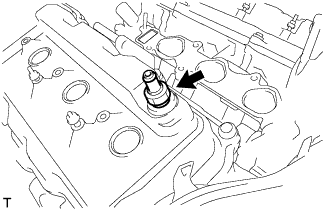

| 3. REMOVE OIL FILLER CAP SUB-ASSEMBLY |
Remove the oil filler cap sub-assembly.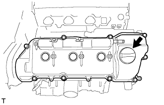
| 4. REMOVE OIL FILLER CAP GASKET |
Remove the oil filler cap gasket.
| 5. REMOVE CYLINDER HEAD COVER SUB-ASSEMBLY |
Remove the 9 bolts and cylinder head cover sub-assembly.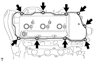
| 6. REMOVE CYLINDER HEAD COVER GASKET |
Remove the cylinder head cover gasket.
| 7. REMOVE CYLINDER HEAD COVER SUB-ASSEMBLY LH |
Remove the 9 bolts and cylinder head cover sub-assembly LH.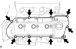
| 8. REMOVE CYLINDER HEAD COVER GASKET NO.2 |
Remove the cylinder head cover gasket No.2.
| 9. REMOVE CAMSHAFT TIMING OIL CONTROL VALVE ASSEMBLY |
Remove the 2 bolts and 2 camshaft timing oil control valve assemblies from the cylinder heads.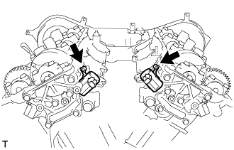
Remove the O-ring from each camshaft timing oil control valve assembly.
| 10. REMOVE VVT SENSOR |
Remove the 2 bolts and 2 VVT sensors.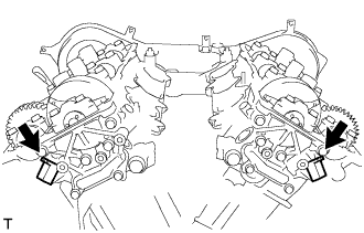
| 11. REMOVE ENGINE OIL LEVEL SENSOR |
Remove the 4 bolts, engine oil level sensor and gasket.
| 12. REMOVE OIL LEVEL GAGE SUB-ASSEMBLY |
Remove the oil level gage sub-assembly from the oil level gage guide.
| 13. REMOVE OIL LEVEL GAGE GUIDE |
Remove the bolt and oil level gage guide.
Remove the O-ring from the oil level gage guide.
| 14. REMOVE CRANKSHAFT PULLEY |
Using SST, loosen the pulley bolt.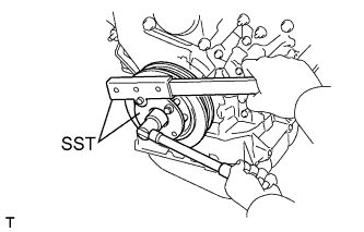
- SST
- 09213-54015
(91651-60855)
09330-00021
Using SST and the pulley bolt, remove the pulley.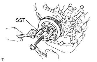
- SST
- 09950-50013
(09951-05010, 09952-05010, 09953-05020, 09954-05031)
- NOTICE:
- Before using SST, apply lubricating oil on the threads and tip of the SST center bolt.
| 15. REMOVE TIMING BELT NO.1 COVER |
Remove the 4 bolts and timing belt No.1 cover.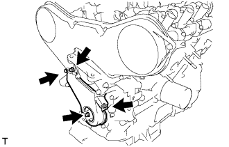
| 16. REMOVE TIMING BELT NO.2 COVER |
Remove the 5 bolts and timing belt No.2 cover.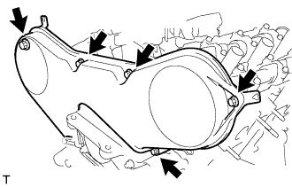
| 17. REMOVE ENGINE MOUNTING BRACKET RH |
Remove the 2 bolts, 2 nuts, and engine mounting bracket RH from the water pump assembly.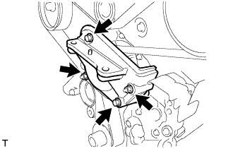
| 18. REMOVE TIMING BELT GUIDE NO.2 |
Remove the timing belt guide No.2 from the crankshaft.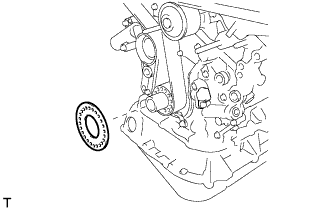
| 19. REMOVE TIMING BELT |
Set No.1 cylinder to TDC/compression.
Temporarily install the crankshaft pulley bolt and washer to the crankshaft.
Turn the crankshaft clockwise, and align the timing marks of the crankshaft timing pulley with the oil pump body.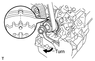
Check that timing marks of the camshaft timing pulleys and No.3 timing belt cover are aligned.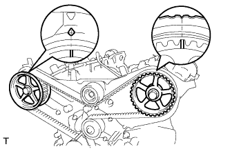
- HINT:
- If not, turn the crankshaft 1 revolution (360°).
Remove the crankshaft pulley bolt.
If reusing the timing belt, check that there are 4 installation marks on the timing belt as shown in the illustration.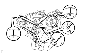
If the installation marks have disappeared, put new installation marks on the timing belt before removing.
Set No.1 cylinder to approximately 60° BTDC/ compression.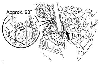
Turn the crankshaft counterclockwise by approximately 60°.
- NOTICE:
- Be sure to set the timing pulley at the correct angle in order to prevent it from being damaged when the timing belt is removed.
- If the timing belt is removed when the crankshaft timing pulley is not installed at the correct angle, the piston head or valve head may come into contact with the pulley and damage it. Make sure that the timing pulley is installed at the correct angle.
- Be sure to set the timing pulley at the correct angle in order to prevent it from being damaged when the timing belt is removed.
Remove the timing belt tensioner.
- NOTICE:
- Do not reinstall the tensioner with its plunger extended.
Remove the timing belt in the following order.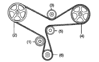
1st
No.1 idler pulley
2nd
RH camshaft timing pulley
3rd
No.2 idler pulley
4th
LH camshaft timing pulley
5th
Water pump pulley
6th
Crankshaft timing pulley
- NOTICE:
- Do not turn the crankshaft or camshaft timing pulley with the timing belt removed. If turned, the piston head or valve head may come into contact with the crankshaft or timing pulley and damage them.
| 20. REMOVE TIMING BELT IDLER SUB-ASSEMBLY NO.1 |
Using a socket hexagon wrench 10 mm, remove the pivot bolt, timing belt idler No.1 and distributor drive gear plate washer.
| 21. REMOVE TIMING BELT IDLER SUB-ASSEMBLY NO.2 |
Remove the bolt and timing belt idler sub-assembly No.2.
| 22. REMOVE CRANKSHAFT POSITION SENSOR |
Remove the bolt and crankshaft position sensor.
| 23. REMOVE CAMSHAFT TIMING PULLEY |
Using SST, remove the bolt and the RH timing pulley.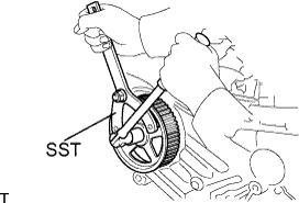
- SST
- 09960-10010
(09962-01000, 09963-01000)
Using SST, remove the bolt and the LH timing pulley.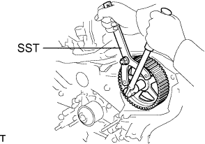
- SST
- 09960-10010
(09962-01000, 09963-01000)
- HINT:
- Arrange the camshaft timing pulleys (RH and LH sides) so that they can be returned to the original locations when reassembling.
| 24. REMOVE TIMING BELT NO.3 COVER |
Remove the 6 bolts and timing belt No.3 cover.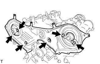
Remove the 6 collars and 6 bushings from the timing belt No.3 cover.
| 25. REMOVE TIMING BELT IDLER BRACKET |
Remove the 2 bolts and timing belt idler bracket.
| 26. REMOVE CRANKSHAFT TIMING PULLEY |
Remove the bolt and the timing belt plate.
Install the pulley bolt to the crankshaft.
Using SST, remove the crankshaft timing pulley.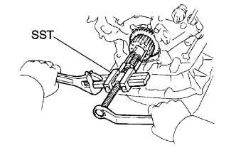
- SST
- 09950-50013
(09951-05010, 09952-05010, 09953-05020, 09954-05011)
- NOTICE:
- Do not scratch the sensor part of the crankshaft timing pulley.
- Before using SST, apply lubricating oil to the threads and tip of the SST center bolt.
- Do not scratch the sensor part of the crankshaft timing pulley.
| 27. REMOVE WATER PUMP ASSEMBLY |
Remove the 3 bolts and 3 nuts, then remove the water pump and the gasket.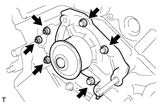
| 28. REMOVE CAMSHAFT |
- NOTICE:
- Since the thrust clearance of the camshaft is small, the camshaft must be kept level while it is being removed. If the camshaft is not kept level, damage to the cylinder head or to the camshaft may result. To avoid this, the following steps should be carried out.
Align the timing marks (2-dot mark) of the camshaft drive and the driven gears by turning the camshaft with a wrench.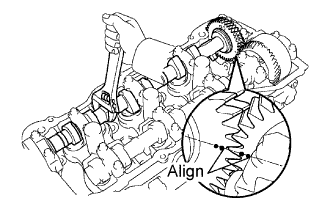
Secure the exhaust camshaft sub-gear to the main gear with a service bolt.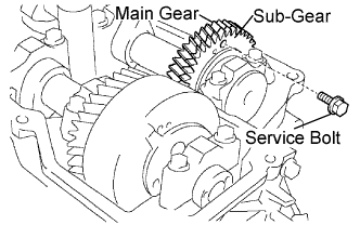
- Torque:
- 5.0 N*m{ 51 kgf*cm , 44 in.*lbf }
Recommended service bolt: Thread diameter
6 mm
Thread pitch
1.0 mm
Bolt length
16 to 20 mm
- HINT:
- When removing the camshaft, make certain that the torsional spring force of the sub-gear has been eliminated by installing the service bolt.
Using several steps, loosen and remove the 10 bearing cap bolts uniformly in the sequence shown in the illustration. Remove the 5 bearing caps and the camshaft.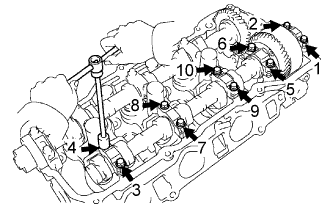
- NOTICE:
- Do not pry out the camshaft.
- Do not damage the portion of the cylinder head which receives the shaft thrust.
- Do not pry out the camshaft.
| 29. REMOVE NO.2 CAMSHAFT |
Using several steps, loosen and remove the 10 bearing cap bolts uniformly in the sequence shown in the illustration. Remove the 5 bearing caps and the No.2 camshaft.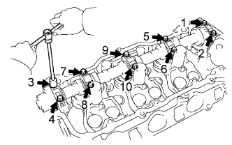
- NOTICE:
- Do not pry out the camshaft.
- Do not damage the portion of the cylinder head which receives the shaft thrust.
- Do not pry out the camshaft.
Remove the oil seal from the No.2 camshaft.
| 30. REMOVE NO.3 CAMSHAFT SUB-ASSEMBLY |
- NOTICE:
- Since the thrust clearance of the camshaft is small, the camshaft must be kept level while it is being removed. If the camshaft is not kept level, damage to the cylinder head or to the camshaft may result. To avoid this, the following steps should be carried out.
Align the timing marks (1-dot mark) of the camshaft drive and the driven gears by turning the camshaft with a wrench.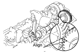
Secure the exhaust camshaft sub-gear to the main gear with a service bolt.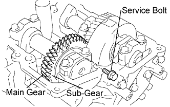
- Torque:
- 5.0 N*m{ 51 kgf*cm , 44 in.*lbf }
Recommended service bolt: Thread diameter
6 mm
Thread pitch
1.0 mm
Bolt length
16 to 20 mm
- HINT:
- When removing the camshaft, make certain that the torsional spring force of the sub-gear has been eliminated by installing the service bolt.
Using several steps, loosen and remove the 10 bearing cap bolts uniformly in the sequence shown in the illustration. Remove the 5 bearing caps and the No.3 camshaft.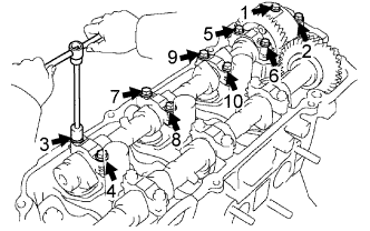
- NOTICE:
- Do not pry out the camshaft.
- Do not damage the portion of the cylinder head which receives the shaft thrust.
- Do not pry out the camshaft.
| 31. REMOVE NO.4 CAMSHAFT SUB-ASSEMBLY |
Using several steps, loosen and remove the 10 bearing cap bolts uniformly in the sequence shown in the illustration. Remove the 5 bearing caps and the No.4 camshaft.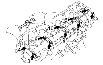
- NOTICE:
- Do not pry out the camshaft.
- Do not damage the portion of the cylinder head which receives the shaft thrust.
- Do not pry out the camshaft.
Remove the oil seal from the No.4 camshaft.
| 32. INSPECT CAMSHAFT TIMING GEAR ASSEMBLY |
Clamp the camshaft in a vise on the hexagonal lobe.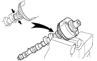
Check that the VVT-i does not turn.
Cover all the oil ports with vinyl tape except the port on the advance angle side (nearest to the convex portion) shown in the illustration.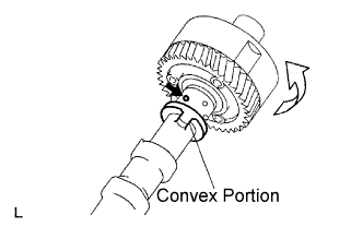
Apply about 100 kPa (1 kgf/cm2, 14 psi) of air pressure to the port on the advance angle side.
- NOTICE:
- Cover the ports with a shop rag or piece of cloth when applying pressure to keep oil from splashing.
- HINT:
- This operation releases the lock pin for the most retard angle lock.
Turn the VVT-i to the advance angle side (the white arrow marked direction in the illustration) by hand.
- Standard:
- The VVT-i turns.
- HINT:
- Depending on the air pressure, the VVT-i will turn to the advance angle side without applying force by hand. Also, if the pressure can be hardly applied because of the air leakage from the port, it might be difficult to get the lock-pin to release.
Check that the VVT-i moves freely within about 30° range. Do not move the VVT-i unit to the most retard angle position as the lock-pin will be engaged again.
- Standard:
- Smooth movable range is about 30°
Turn the VVT-i by hand and lock it at the most retard angle position.
| 33. REMOVE CAMSHAFT TIMING GEAR ASSEMBLY |
- NOTICE:
- Do not remove or install the camshaft timing gear (VVT-i) unless the VVT-i or the camshaft needs to be replaced.
Clamp the camshaft in a vise on the hexagonal lobe.
- NOTICE:
- Do not damage the camshaft.
Using a 46 mm socket wrench, remove the lock nut by turning it clockwise.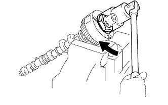
- NOTICE:
- Remove it with the lock-pin engaged and locked at the most retard angle position.
- The lock nut has left-hand threads.
- Never use any tool other than the socket wrench. Other tools will deform the cam angle rotor.
- Remove it with the lock-pin engaged and locked at the most retard angle position.
Remove the camshaft VVT-i.
- NOTICE:
- Never remove the 3 bolts on the gear.
| 34. REMOVE CAMSHAFT SUB GEAR |
Clamp the camshaft in a vise on the hexagonal lobe.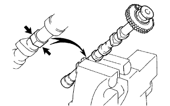
- NOTICE:
- Do not damage the camshaft.
Using SST, turn the sub-gear counterclockwise, and remove the service bolt.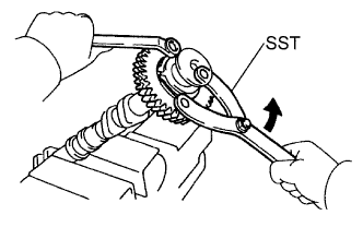
- SST
- 09960-10010
(09962-01000, 09963-00500)
Using snap ring pliers, remove the snap ring.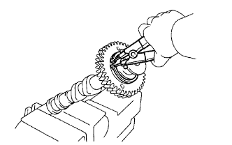
Remove the wave washer, camshaft sub-gear and camshaft gear bolt washer.
- HINT:
- Arrange the camshaft sub-gears and gear bolt washers (RH and LH sides) so that they can be returned to the original locations when re-assembling.
| 35. REMOVE ENGINE HANGER NO.2 |
Remove the 2 bolts and engine hanger No.2 from the cylinder head.
| 36. REMOVE CYLINDER HEAD COVER REAR |
Remove the 12 bolts, nut and cylinder head cover rear from the cylinder head.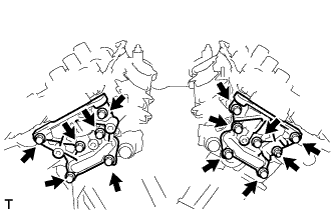
| 37. REMOVE OIL CONTROL VALVE FILTER |
Remove the plug, gasket and valve filter.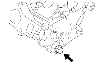
| 38. REMOVE CYLINDER HEAD SUB-ASSEMBLY |
Using a socket hexagon wrench 8 mm, remove the hexagon bolt.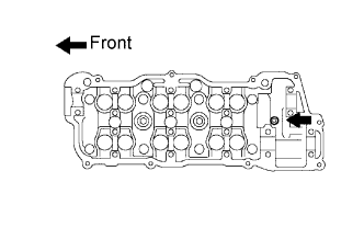
Using several steps, loosen the 8 cylinder head bolts uniformly in the sequence shown in the illustration. Remove the 8 cylinder head bolts and plate washers.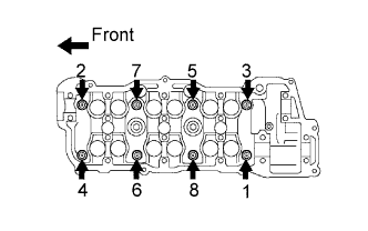
- NOTICE:
- Do not drop the washers into the cylinder head.
- Head warpage or cracking could result from removing bolts in an incorrect order.
- Do not drop the washers into the cylinder head.
| 39. REMOVE CYLINDER HEAD GASKET |
Remove the cylinder head gasket from the cylinder block.
| 40. REMOVE CYLINDER HEAD LH |
Using a socket hexagon wrench 8 mm, remove the hexagon bolt.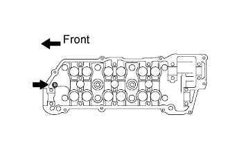
Using several steps, loosen the 8 cylinder head bolts uniformly in the sequence shown in the illustration. Remove the 8 cylinder head bolts and plate washers.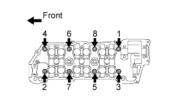
- NOTICE:
- Do not drop the washers into the cylinder head.
- Head warpage or cracking could result from removing bolts in an incorrect order.
- Do not drop the washers into the cylinder head.
| 41. REMOVE CYLINDER HEAD GASKET NO.2 |
Remove the cylinder head gasket No.2 from the cylinder block.
| 42. REMOVE WATER INLET HOUSING |
Remove the 8 bolts and 2 nuts, then remove the water inlet housing.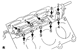
| 43. REMOVE OIL FILTER SUB-ASSEMBLY |
Using SST, remove the oil filter.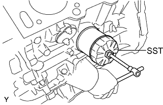
- SST
- 09228-07501
Using a socket hexagon wrench 12 mm, remove the oil filter union.
| 44. REMOVE OIL PAN DRAIN PLUG |
Remove the oil pan drain plug and gasket.
| 45. REMOVE OIL PAN SUB-ASSEMBLY NO.2 |
Remove the 10 bolts and 2 nuts.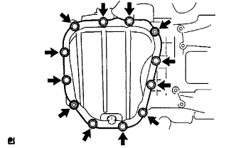
Insert the blade of SST between oil pan and oil pan No.2, cut off the sealer and remove the oil pan No.2.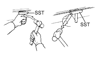
- SST
- 09032-00100
- NOTICE:
- Do not damage the contact surfaces of oil pan and oil pan No.2.
- Do not damage the flange portion of oil pan No.2 when removing.
- Do not damage the contact surfaces of oil pan and oil pan No.2.
| 46. REMOVE OIL STRAINER SUB-ASSEMBLY |
Remove the bolt and 2 nuts, then remove the oil strainer and the gasket.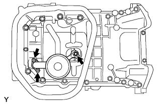
| 47. REMOVE OIL PAN SUB-ASSEMBLY |
Loosen and remove the 17 bolts uniformly.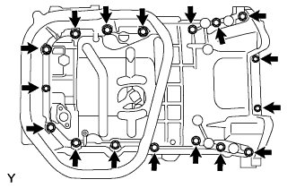
Using a screwdriver, remove the oil pan by prying between the cylinder block and the oil pan.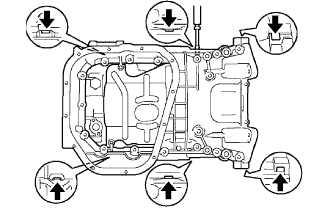
- NOTICE:
- Do not damage the contact surfaces of the oil pan and cylinder block.
| 48. REMOVE OIL PAN BAFFLE PLATE |
Remove the 6 bolts and the oil pan baffle plate from the oil pan.
| 49. REMOVE ENGINE REAR OIL SEAL RETAINER |
Remove the 6 bolts.
Using a screwdriver, remove the oil seal retainer by prying between the oil seal retainer and the main bearing cap.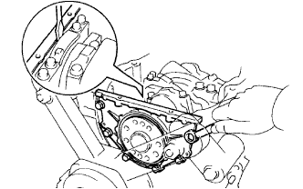
| 50. REMOVE ENGINE REAR OIL SEAL |
Using a screwdriver and a hammer, tap out the oil seal.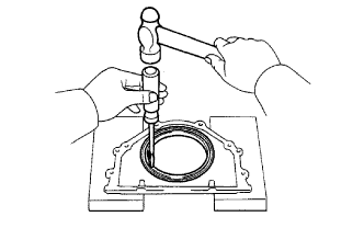
| 51. REMOVE OIL PUMP ASSEMBLY |
Remove the 9 bolts.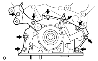
Using a screwdriver, remove the oil pump by prying between the oil pump and the main bearing cap.
Remove the O-ring.
| 52. REMOVE OIL PUMP SEAL |
Using a screwdriver, pry out the oil seal.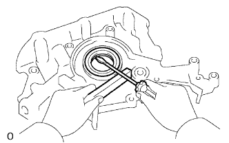
| 53. REMOVE SPARK PLUG TUBE GASKET |
Bend up the tab on the ventilation baffle plate which prevents the gasket from slipping out.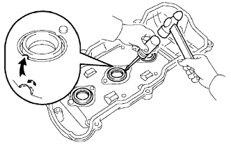
- NOTICE:
- Do not damage the baffle plate of the cylinder head cover.
Using a screwdriver and a hammer, tap out the gasket.
Using needle-nose pliers, pry out the gasket.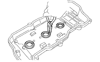
- NOTICE:
- Do not damage the cylinder head cover.
| 54. INSPECT TIMING BELT |
- NOTICE:
- Do not bend, twist or turn the timing belt inside out.
- Do not allow the timing belt to come into contact with oil, water or steam.
- Do not utilize timing belt tension when installing or removing the mounting bolt of the camshaft timing pulley.
- Do not bend, twist or turn the timing belt inside out.
If there is premature parting: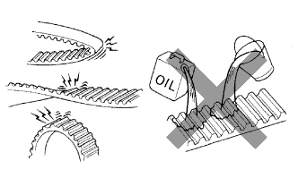
- Check for proper installation.
- Check the timing cover gasket for damage and proper installation.
- Check for proper installation.
If the belt teeth are cracked or damaged, check if either camshaft is locked.
If there is noticeable wear or cracks on the belt face, check if there are nicks on the side of the idler pulley lock and water pump.
If there is wear or damage to only one side of the belt, check the belt guide and the alignment of each pulley.
If there is noticeable wear on the belt teeth:
- Check the timing cover for damage.
- Check that the gasket has been installed correctly.
- Check for foreign object on the pulley teeth.
- Check the timing cover for damage.
| 55. INSPECT CAMSHAFT |
Inspect camshaft for runout.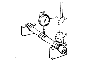
Place the camshaft on V-blocks.
Using a dial indicator, measure the runout at the center journal.
- Maximum circle runout:
- 0.06 mm (0.0024 in.)
Inspect cam lobes.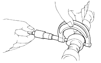
Using a micrometer, measure the cam lobe height.
- Standard cam lobe height:
- Intake:
- 43.132 to 43.232 mm (1.6981 to 1.7020 in.)
- Exhaust:
- 43.010 to 43.110 mm (1.6933 to 1.6972 in.)
- Minimum cam lobe height:
- Intake:
- 42.98 mm (1.6921 in.)
- Exhaust:
- 42.86 mm (1.6874 in.)
Inspect camshaft journals.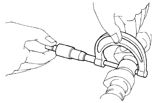
Using a micrometer, measure the journal diameter.
- Journal diameter:
- 26.959 to 26.975 mm (1.0614 to 1.0620 in.)
| 56. INSPECT CYLINDER HEAD SET BOLT |
Using vernier calipers, measure the tension portion diameter of the bolt.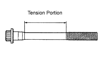
- Standard outside diameter:
- 8.95 to 9.05 mm (0.3524 to 0.3563 in.)
- Minimum outside diameter:
- 8.75 mm (0.3445 in.)
| 57. REMOVE W/ HEAD STRAIGHT SCREW PLUG NO.1 (RH CYLINDER) |
Using a hexagon wrench 14 mm, remove the 2 straight screw plugs and 2 gaskets.
| 58. REMOVE W/ HEAD STRAIGHT SCREW PLUG NO.2 (LH CYLINDER) |
Using a hexagon wrench 14 mm, remove the 2 straight screw plugs and 2 gaskets.
| 59. REMOVE VALVE LIFTER |
- HINT:
- Store the lifters in the correct order so that they can be returned to the original locations when reassembling.
| 60. REMOVE INTAKE VALVE |
Using SST, compress the valve spring and remove the 2 retainer locks, retainer, spring and valve.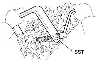
- SST
- 09202-70020
(09202-00010)
- HINT:
- Store the valves, valve springs and spring retainers in the correct order so that they can be returned to the original locations when reassembling.
| 61. REMOVE EXHAUST VALVE |
Using SST, compress the valve spring and remove the 2 retainer locks, retainer, spring and valve.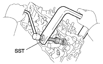
- SST
- 09202-70020
(09202-00010)
- HINT:
- Store the valves, valve springs and spring retainers in the correct order so that they can be returned to the original locations when reassembling.
| 62. REMOVE VALVE STEM OIL SEAL OR RING |
Using needle-nose pliers, remove the oil seals.
| 63. REMOVE VALVE SPRING SEAT |
Remove the valve spring seats from the cylinder head.
| 64. REMOVE SEMICIRCULAR PLUG |
Remove the semicircular plug from the cylinder head.
| 65. INSPECT CYLINDER HEAD FOR FLATNESS |
Using a precision straight edge and a feeler gauge, measure the warpage of the contacting surface between the cylinder block and the manifolds.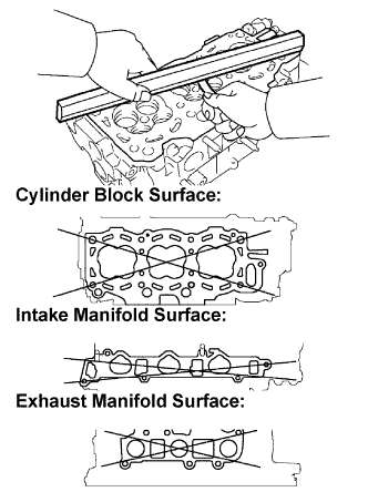
- Maximum warpage:
- Cylinder block surface:
- 0.05 mm (0.0020 in.)
- Intake manifold surface:
- 0.10 mm (0.0039 in.)
- Exhaust manifold surface:
- 0.10 mm (0.0039 in.)
| 66. INSPECT CYLINDER HEAD FOR CRACKS |
Using a dye penetrant, check the combustion chamber, intake ports, exhaust ports and cylinder block surface for cracks.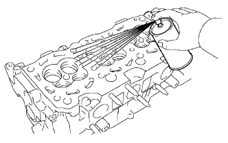
If cracked, replace the cylinder head.
| 67. INSPECT INTAKE VALVE |
Check the valve overall length.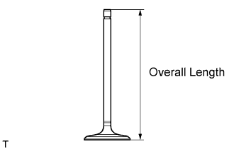
- Standard overall length:
- 95.45 mm (3.7579 in.)
- Minimum overall length:
- 94.95 mm (3.7382 in.)
Using a micrometer, measure the diameter of the valve stem.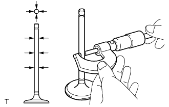
- Valve stem diameter:
- 5.470 to 5.485 mm (0.2154 to 0.2159 in.)
Check the valve head margin thickness.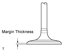
- Standard margin thickness:
- 1.0 mm (0.039 in.)
- Minimum margin thickness:
- 0.5 mm (0.020 in.)
| 68. INSPECT EXHAUST VALVE |
Check the valve overall length.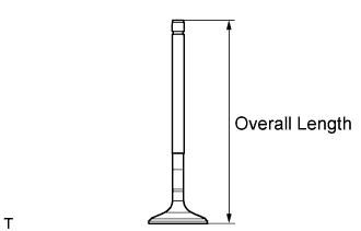
- Standard overall length:
- 95.40 mm (3.7559 in.)
- Minimum overall length:
- 94.90 mm (3.7362 in.)
Using a micrometer, measure the diameter of the valve stem.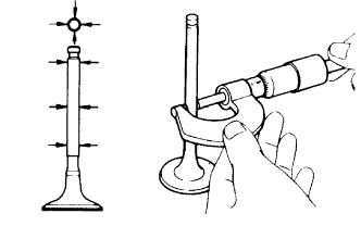
- Valve stem diameter:
- 5.465 to 5.480 mm (0.2152 to 0.2157 in.)
Check the valve head margin thickness.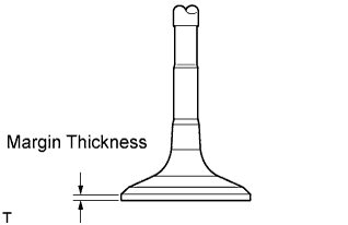
- Standard margin thickness:
- 1.0 mm (0.039 in.)
- Minimum margin thickness:
- 0.5 mm (0.020 in.)
| 69. INSPECT INNER COMPRESSION SPRING |
Using vernier calipers, measure the free length of the valve spring.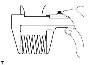
- Free length:
- 45.50 mm (1.7913 in.)
Using a steel square, measure the deviation of the valve spring.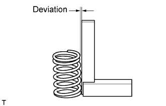
- Maximum deviation:
- 2.0 mm (0.079 in.)
Using a spring tester, measure the tension of the valve spring at the specified installed length.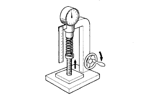
- Installed tension:
- 186 to 206 N (19.0 to 21.0 kgf, 41.9 to 46.3 lbf) at 33.8 mm (1.331 in.)
| 70. INSPECT VALVE GUIDE BUSHING OIL CLEARANCE |
Using a caliper gauge, measure the inside diameter of the guide bushing.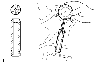
- Bushing inside diameter:
- 5.510 to 5.530 mm (0.2169 to 0.2177 in.)
Subtract the valve stem diameter measurement from the guide bushing inside diameter measurement.
- Standard oil clearance:
- Intake:
- 0.025 to 0.060 mm (0.0010 to 0.0024 in.)
- Exhaust:
- 0.030 to 0.065 mm (0.0012 to 0.0026 in.)
- Maximum oil clearance:
- Intake:
- 0.08 mm (0.0031 in.)
- Exhaust:
- 0.10 mm (0.0039 in.)
| 71. REMOVE VALVE GUIDE BUSH |
Heat the cylinder head to 80 to 100°C (176 to 212°F).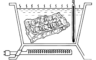
Using SST and a hammer, tap out the guide bush.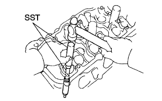
- SST
- 09201-10000
(09201-01055)
09950-70010 (09951-07100)
| 72. INSTALL VALVE GUIDE BUSH |
Using a caliper gauge, measure the bush bore diameter of the cylinder head.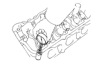
- Diameter:
- 10.295 to 10.313 mm (0.4053 to 0.4060 in.)
- HINT:
- Using a caliper gauge, measure of the cylinder head.
- Bush diameter:
Bush diameter
STD
10.333 to 10.344 mm (0.4068 to 0.4072 in.)
O/S
10.383 to 10.394 mm (0.4088 to 0.4092 in.)
Using vernier calipers, measure the new bush length.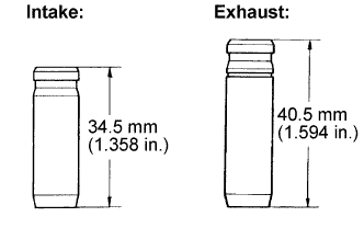
- HINT:
- Using vernier calipers, measure of the bush.
- Bush length:
Bush length
Intake
34.5 mm (1.358 in.)
Exhaust
40.5 mm (1.594 in.)
Heat the cylinder head to 80 to 100°C (176 to 212°F)
Using SST and a hammer, tap in a new guide bush to the specified protrusion height.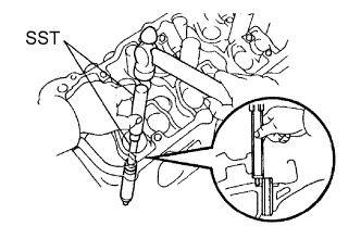
- SST
- 09201-10000
(09201-01055)
09950-70010 (09951-07100)
- Protrusion height:
- Intake:
- 11.1 to 11.5 mm (0.437 to 0.453 in.)
- Exhaust:
- 8.9 to 9.3 mm (0.350 to 0.366 in.)
Using a sharp 5.5 mm reamer, ream the guide bush to obtain the standard specified clearance between the guide bush and the valve stem.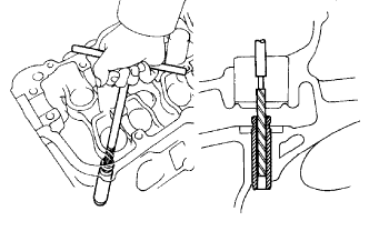
- Standard oil clearance:
- Intake:
- 0.025 to 0.060 mm (0.0010 to 0.0024 in.)
- Exhaust:
- 0.030 to 0.065 mm (0.0012 to 0.0026 in.)
| 73. INSPECT VALVE SEATS |
Apply a light coat of prussian blue (or white lead) to the valve face.
Lightly press the valve against the seat.
- NOTICE:
- Do not rotate the valve.
Check the valve face and seat according to the following procedure.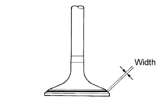
If prussian blue appears around the entire face, the valve is concentric. If not, replace the valve.
If prussian blue appears around the entire valve seat, the guide and face are concentric. If not, resurface the seat.
Check that the seat contacts in the middle of the valve face with the width between 1.0 and 1.4 mm (0.039 and 0.055 in.).
| 74. REPAIR VALVE SEATS |
- NOTICE:
- Releasing the seat-cutter pressure gradually helps to make smoother valve seat faces.
If the seating is too high on the valve face, use 30° and 45° cutters to correct the seat.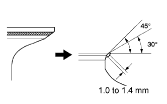
If the seating is too low on the valve face, use 60° and 45° cutters to correct the seat.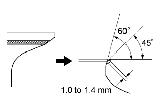
Handrub the valve and valve seat with an abrasive compound.
Recheck the valve seating position.
| 75. INSPECT VALVE LIFTER |
Using a micrometer, measure the lifter diameter.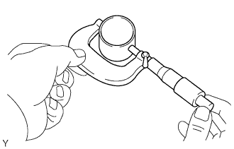
- Lifter diameter:
- 30.966 to 30.976 mm (1.2191 to 1.2195 in.)
| 76. INSPECT VALVE LIFTER OIL CLEARANCE |
Using a caliper gauge, measure the lifter bore diameter of the cylinder head.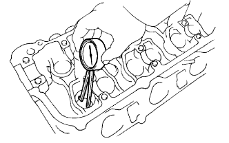
- Lifter bore diameter:
- 31.009 to 31.025 mm (1.2208 to 1.2215 in.)
Subtract the lifter diameter measurement from the lifter bore diameter measurement.
- Standard oil clearance:
- 0.033 to 0.059 mm (0.0013 to 0.0023 in.)
- Maximum oil clearance:
- 0.07 mm (0.0028 in.)
| 77. INSPECT CAMSHAFT GEAR BACKLASH |
Install camshaft timing gear assembly.
Install the camshafts to the cylinder head.
- NOTICE:
- Install without valves and sub-gear.
- Install with its timing mark matched.
- Install without valves and sub-gear.
Set the dial indicator to the teeth of the intake camshaft at a right angle (90°).
Measure the backlash of the camshaft timing gear at least 4 positions.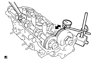
- Standard backlash:
- 0.020 to 0.200 mm (0.0008 to 0.0079 in.)
- Maximum backlash:
- 0.30 mm (0.0118 in.)
| 78. INSPECT CAMSHAFT THRUST CLEARANCE |
Install the camshafts.
Using a dial indicator, measure the thrust clearance while moving the camshaft back and forth.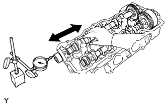
- Standard thrust clearance:
- 0.040 to 0.090 mm (0.0016 to 0.0035 in.)
- Maximum thrust clearance:
- 0.12 mm (0.0047 in.)
| 79. INSPECT CAMSHAFT OIL CLEARANCE |
Clean the bearing caps and camshaft journals.
Place the camshafts on the cylinder head.
Lay a strip of Plastigage across each of the camshaft journal.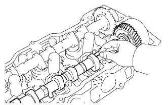
Install the bearing caps.
- Torque:
- 16 N*m{ 163 kgf*cm , 12 ft.*lbf }
- NOTICE:
- Do not turn the camshaft.
Remove the bearing caps.
Measure the Plastigage at its widest point.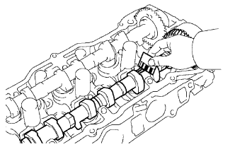
- Standard oil clearance:
- Intake #4, #5 journals:
- 0.025 to 0.057 mm (0.0010 to 0.0022 in.)
- Other journals:
- 0.025 to 0.062 mm (0.0010 to 0.0024 in.)
- Maximum oil clearance:
- 0.10 mm (0.0039 in.)
- NOTICE:
- Completely remove the Plastigage.
| 80. REMOVE CYLINDER BLOCK WATER DRAIN COCK SUB-ASSEMBLY |
Remove the water drain cock sub-assembly from the cylinder block.
| 81. REMOVE WATER SEAL PLATE |
Remove the 2 nuts and water seal plate from the cylinder block.
| 82. REMOVE CYLINDER BLOCK W/ HEAD STRAIGHT SCREW NO.1 PLUG |
Using a socket hexagon wrench 10 mm, remove the straight screw No.1 plug and gasket.
| 83. REMOVE CYLINDER BLOCK W/ HEAD STRAIGHT SCREW NO.2 PLUG |
Using a socket hexagon wrench 10 mm, remove the straight screw No.2 plug and gasket.
| 84. REMOVE CYLINDER BLOCK W/ HEAD STRAIGHT SCREW NO.3 PLUG |
Using a socket hexagon wrench 10 mm, remove the straight screw No.3 plug and gasket.
| 85. INSPECT CONNECTING ROD THRUST CLEARANCE |
Using a dial indicator, measure the thrust clearance while moving the connecting rod back and forth.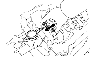
- Standard thrust clearance:
- 0.15 to 0.30 mm (0.0059 to 0.0118 in.)
- Maximum thrust clearance:
- 0.35 mm (0.0138 in.)
| 86. INSPECT CONNECTING ROD OIL CLEARANCE |
Check that the matchmarks on the connecting rod and cap are aligned to ensure correct reassembly.
Remove the 2 connecting rod cap bolts.
Clean the crank pin, the bearing and the connecting rod.
Check the crank pin and bearing for pits and scratches.
Lay a strip of Plastigage across the crank pin.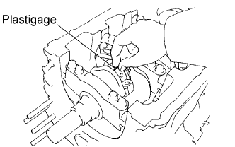
Check that the protrusion of the connecting rod cap is facing the correct direction.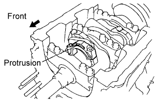
Apply a light coat of engine oil to the threads of the connecting rod cap bolts.
Tighten the bolts in several steps to the specified torque.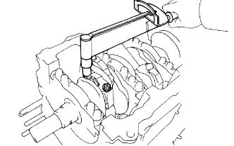
- Torque:
- 25 N*m{ 255 kgf*cm , 18 ft.*lbf }
Mark the front side of each connecting cap bolt with paint.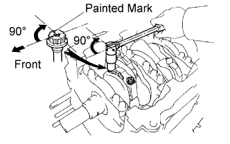
Retighten the cap bolts by 90° as shown in the illustration.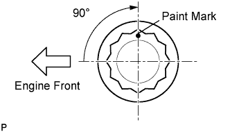
- NOTICE:
- Do not turn the crankshaft.
Remove the 2 bolts, the connecting rod cap and the lower bearing.
Measure the Plastigage at its widest point.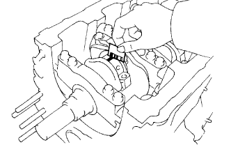
- Standard oil clearance:
- 0.038 to 0.066 mm (0.0015 to 0.0026 in.)
- Maximum oil clearance:
- 0.08 mm (0.0031 in.)
- NOTICE:
- Completely remove the Plastigage.
If replacing the bearing, replace it with one having the same number as marked on the connecting rod.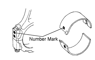
Mark
mm (in.)
"1"
1.484 to 1.487 (0.0584 to 0.0585)
"2"
1.488 to 1.490 (0.0586 to 0.0587)
"3"
1.491 to 1.493 (0.0587 to 0.0588)
"4"
1.494 to 1.496 (0.0588 to 0.0589)
- HINT:
- Standard bearing center wall thickness
- There are 4 sizes of standard bearings, marked "1", "2", "3" and "4" accordingly.
- Standard bearing center wall thickness
| 87. REMOVE PISTON SUB-ASSEMBLY W/ CONNECTING ROD |
Using a ridge reamer, remove all the carbon from the top of the cylinder.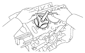
Push out the piston and the connecting rod assembly from the top of the cylinder block.
- HINT:
- Keep the bearings, the connecting rod and the cap together.
- Arrange the piston and the connecting rod assemblies in the correct order so they can be returned to the original locations when re-assembling.
- Keep the bearings, the connecting rod and the cap together.
| 88. REMOVE CONNECTING ROD BEARING |
Remove the connecting rod bearing from the connecting rod and connecting rod bearing cap.
| 89. REMOVE PISTON RING SET |
Using a piston ring expander, remove the 2 compression rings.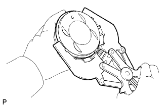
Using a piston ring expander, remove the oil ring side rail.
Remove the oil ring expander by hand.
| 90. REMOVE PISTON PIN HOLE SNAP RING |
Using a screwdriver, pry out the 2 snap rings.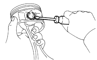
| 91. REMOVE W/ PIN PISTON SUB-ASSEMBLY |
Gradually heat the piston to approximately 80°C (176°F).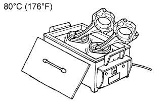
Using a plastic hammer and a brass bar, lightly tap out the piston pin and remove the connecting rod.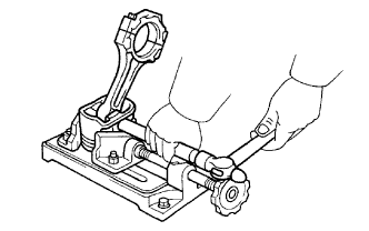
- HINT:
- The piston and pin are a matched set.
- Store the pistons, the pins, the rings, the connecting rods and the bearings in the correct order so that they can be returned to the original locations when reassembling.
- The piston and pin are a matched set.
| 92. INSPECT CRANKSHAFT THRUST CLEARANCE |
Using a dial indicator, measure the thrust clearance while prying the crankshaft back and forth with a screwdriver.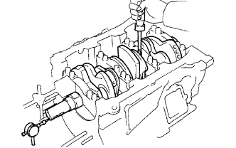
- Standard thrust clearance:
- 0.04 to 0.24 mm (0.0016 to 0.0094 in.)
- Maximum thrust clearance:
- 0.30 mm (0.0118 in.)
- HINT:
- Thrust washer thickness is 1.93 to 1.98 mm (0.0760 to 0.0780 in.)
| 93. REMOVE CRANKSHAFT |
Using several steps, loosen and remove the 8 main bearing cap bolts and seal washers uniformly in the sequence shown in the illustration.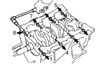
Using several steps, loosen and remove the 16 main bearing cap bolts uniformly in the sequence shown in the illustration.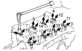
Using a screwdriver, pry out the main bearing caps. Remove the 4 main bearing caps and the lower bearings.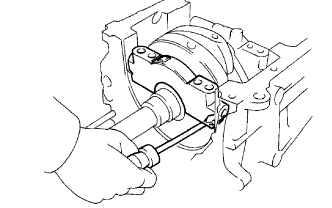
- NOTICE:
- Carefully pry out the main bearing cap by alternating lifting a little at a time on each end of the cap.
- Do not damage the joint surface of the cylinder block and the main bearing cap.
- Carefully pry out the main bearing cap by alternating lifting a little at a time on each end of the cap.
Check the damaged the joint surface of the cylinder block and the main bearing cap.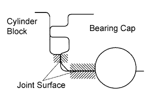
| 94. REMOVE CRANKSHAFT THRUST WASHER SET |
Remove the crankshaft thrust washer set.
| 95. REMOVE CRANKSHAFT BEARING |
Remove the crankshaft bearing from the cylinder block and crankshaft bearing cap.
| 96. INSPECT CYLINDER BLOCK FOR FLATNESS |
Using a precision straight edge and feeler gauge, measure the warpage of the contacting surface of the cylinder head gasket.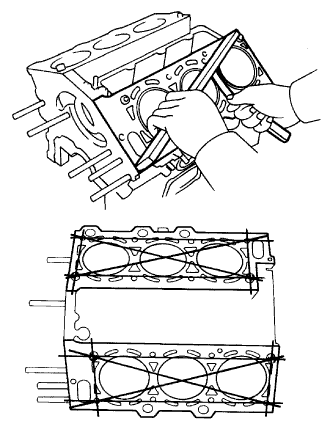
- Maximum warpage:
- 0.05 mm (0.0020 in.)
| 97. INSPECT CYLINDER BORE |
Using a cylinder gauge, measure the cylinder bore diameter at positions A and B in the thrust and axial directions.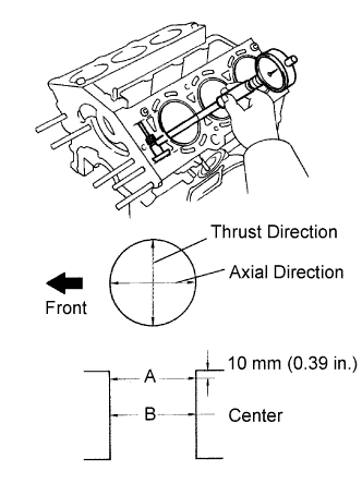
- Standard diameter:
- 92.000 to 92.012 mm (3.6220 to 3.6225 in.)
- Maximum diameter:
- 92.132 mm (3.6272 in.)
| 98. INSPECT W/ PIN PISTON SUB-ASSEMBLY |
Using a micrometer, measure the diameter of the piston. When measuring the diameter, attach the micrometer to a location where 13.0 mm (0.512 in.) above from the piston bottom at the right angles to the piston pin hole.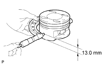
- Piston diameter:
- 91.975 to 91.989 mm (3.6211 to 3.6216 in.)
| 99. INSPECT PISTON OIL CLEARANCE |
Subtract the piston diameter measurement from the cylinder bore diameter measurement.
- Standard oil clearance:
- 0.033 to 0.059mm (0.0013 to 0.0023 in.)
- Maximum oil clearance:
- 0.13 mm (0.0051 in.)
| 100. INSPECT CONNECTING ROD |
Using a rod aligner and feeler gauge, check the connecting rod alignment.
Check for misalignment.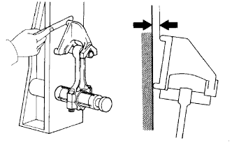
- Maximum misalignment:
- 0.05 mm (0.0020 in.) per 100 mm (3.94 in.)
Check for twist.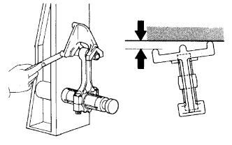
- Maximum twist:
- 0.15 mm (0.0059 in.) per 100 mm (3.94 in.)
| 101. INSPECT PISTON PIN OIL CLEARANCE |
Using a caliper gauge, measure the inside diameter of the connecting rod bushing.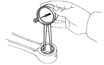
- Bushing inside diameter:
- 22.005 to 22.014 mm (0.8663 to 0.8667 in.)
Using a micrometer, measure the piston pin diameter.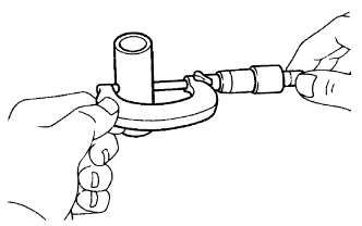
- Piston pin diameter:
- 21.997 to 22.006 mm (0.8660 to 0.8664 in.)
Subtract the piston pin diameter measurement from the bushing inside diameter measurement.
- Standard oil clearance:
- 0.005 to 0.011 mm (0.0002 to 0.0004 in.)
- Maximum oil clearance:
- 0.05 mm (0.0020 in.)
| 102. REMOVE CONNECTING ROD SMALL END BUSH |
Using SST and a press, press out the bushing.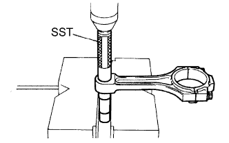
- SST
- 09222-30010
| 103. INSTALL CONNECTING ROD SMALL END BUSH |
Align the oil holes of a new bushing and the connecting rod.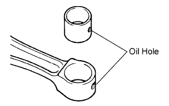
Using SST and a press, press in the bushing.
- SST
- 09222-30010
Using a pin hole grinder, hone the bushing to obtain the standard specified clearance between the bushing and piston pin.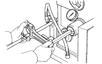
- Standard oil clearance:
- 0.005 to 0.011 mm (0.0002 to 0.0004 in.)
Check the piston pin fit at normal room temperature, coat the piston pin with engine oil, and push it into the connecting rod with your thumb.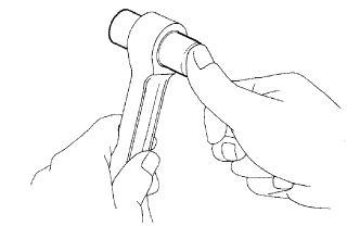
| 104. INSPECT RING GROOVE CLEARANCE |
Using a feeler gauge, measure the clearance between a new piston ring and the wall of the ring groove.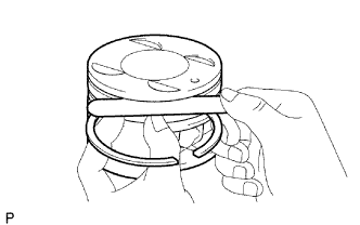
- Ring groove clearance:
Item
Specified Condition
No.1
0.03 to 0.08 mm (0.0012 to 0.0031 in.)
No.2
0.02 to 0.06 mm (0.0008 to 0.0024 in.)
Oil (Side rail)
0.03 to 0.11 mm (0.0012 to 0.0043 in.)
| 105. INSPECT PISTON RING END GAP |
Using a piston, push the piston ring a little beyond the bottom of the ring travel, 110 mm (4.33 in.) from the top of the cylinder block.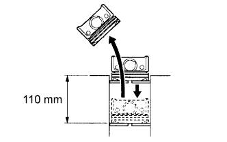
Using a feeler gauge, measure the end gap.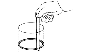
- Standard end gap:
Item
Specified Condition
No.1
0.30 to 0.40 mm (0.0118 to 0.0157 in.)
No.2
0.50 to 0.60 mm (0.0197 to 0.0236 in.)
Oil (Side rail)
0.15 to 0.40 mm (0.0059 to 0.0157 in.)
- Maximum end gap:
Item
Specified Condition
No.1
0.95 mm (0.0374 in.)
No.2
1.05 mm (0.0413 in.)
Oil (Side rail)
1.00 mm (0.0394 in.)
If the end gap is greater than the maximum even with a new piston ring, replace the cylinder block.
| 106. INSPECT CONNECTING ROD BOLT |
Using vernier calipers, measure the tension portion diameter of the bolt.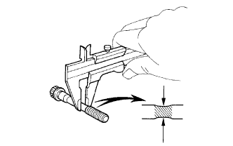
- Standard diameter:
- 7.2 to 7.3 mm (0.283 to 0.287 in.)
- Minimum diameter:
- 7.0 mm (0.276 in.)
| 107. INSPECT CRANKSHAFT BEARING CAP SET BOLT |
Using vernier calipers, measure the tension portion diameter of the bolt.
- Standard diameter:
- 7.5 to 7.6 mm (0.295 to 0.299 in.)
- Minimum diameter:
- 7.2 mm (0.283 in.)
| 108. INSPECT CRANKSHAFT |
Using a dial indicator and V-blocks, measure the runout as shown in the illustration.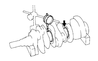
- Maximum circle runout:
- 0.06 mm (0.0024 in.)
Using a micrometer, measure the diameter of each main journal.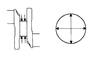
- Diameter:
- 60.988 to 61.000 mm (2.4011 to 2.4016 in.)
Check each main journal for taper and out-of-round as shown.
- Maximum taper and out-of-round:
- 0.02 mm (0.0008 in.)
Using a micrometer, measure the diameter of each crank pin.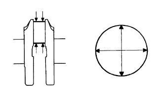
- Diameter:
- 52.992 to 53.000 mm (2.0863 to 2.0866 in.)
Check each crank pin for taper and out-of-round as shown.
- Maximum taper and out-of-round:
- 0.02 mm (0.0008 in.)
| 109. INSPECT CRANKSHAFT OIL CLEARANCE |
Clean each main journal and bearing.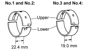
- HINT:
- Main bearings come in widths of 22.4 mm (0.882 in.) and 19.0 mm (0.748 in.). Install the 22.4 mm (0.882 in.) bearings in the No.1 and No.2 cylinder block journal positions with the main bearing cap. Install the 19.0 mm (0.748 in.) bearings in the No.3 and No.4 positions.
Align the bearing key with the keyway of the cylinder block, and push in the 4 upper bearings.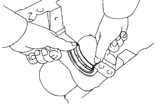
- NOTICE:
- Do not apply engine oil to the bearing and its contact surface.
Align the bearing key with the keyway of the main bearing cap, and push in the 4 lower bearings.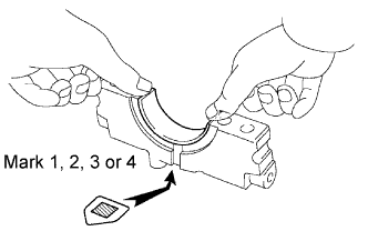
- NOTICE:
- Do not apply engine oil to the bearing and its contact surface.
- HINT:
- A number is marked on each main bearing cap to indicate the installation position.
Place the crankshaft on the cylinder block.
Lay a strip of Plastigage across each journal.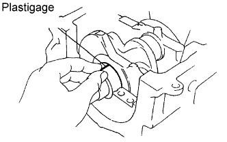
Examine the front marks and numbers and install the bearing caps on the cylinder block.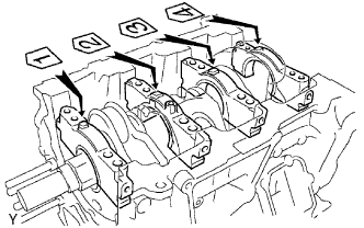
Apply a light coat of engine oil to the threads of the bearing cap bolts.
Temporarily install the 8 main bearing cap bolts to the inside positions.
Install the main bearing cap by hand until clearance between the cylinder block and the bearing cap becomes 6 mm (0.23 in.) or less.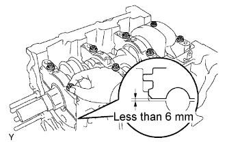
Using a plastic-faced hammer, lightly tap the bearing cap to ensure a proper fit.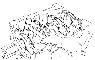
Apply a light coat of engine oil to the threads of the main bearing cap bolts.
Using several steps, install and tighten the 16 main bearing cap bolts uniformly in the sequence shown in the illustration.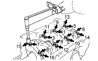
- Torque:
- 22 N*m{ 224 kgf*cm , 16 ft.*lbf }
Mark the front side of the bearing cap bolts with paint.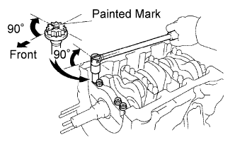
Retighten the bearing cap bolts by 90° in the same sequence shown as step (l).
Check that each painted mark is now at a 90° angle to the front.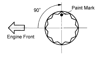
- NOTICE:
- Do not turn the crankshaft.
Using several steps, install and tighten the 8 main bearing cap bolts uniformly in the sequence shown in the illustration.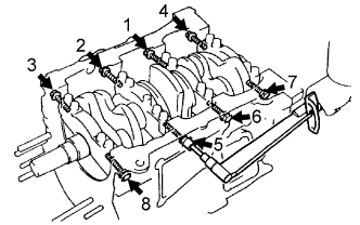
- Torque:
- 27 N*m{ 275 kgf*cm , 20 ft.*lbf }
- HINT:
- Use the short bolt for the marked position (arrow).
Remove the main bearing caps.
Measure the Plastigage at its widest point.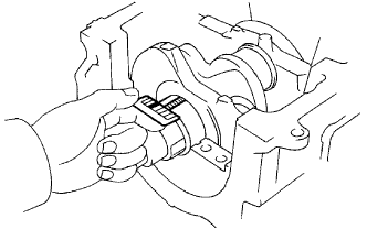
- Standard oil clearance:
- No.1 and No.2 journals:
- 0.014 to 0.031 mm (0.0006 to 0.0012 in.)
- No.3 and No.4 journals:
- 0.026 to 0.043 mm (0.0010 to 0.0017 in.)
- Maximum clearance:
- No.1 and No.2 journals:
- 0.05 mm (0.0020 in.)
- No.3 and No.4 journals:
- 0.06 mm (0.0024 in.)
- NOTICE:
- Completely remove the Plastigage.
If replacing a bearing, replace it with one having the same number. If the number of the bearing cannot be determined, select the correct bearing by adding together the numbers imprinted on the cylinder block and crankshaft, then refer to the table below for the appropriate bearing number. The No.1 and No.2 journal bearings come in sizes, marked "3", "4", "5", "6" and "7". The No.3 and No.4 journal bearings come in 5 standard bearing sizes, marked "1", "2", "3", "4" and "5".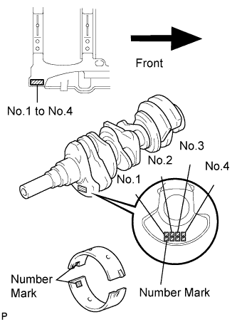
No.1 and No.2 journal standard bearings selection chart Crankshaft
number mark
Cylinder block number mark
00
01
02
03
04
05
06
07
08
09
10
11
12
13
14
15
16
00
3
3
3
3
4
4
4
4
4
4
4
5
5
5
5
5
5
01
3
3
4
4
4
4
4
4
4
4
5
5
5
5
5
5
5
02
3
4
4
4
4
4
4
4
5
5
5
5
5
5
5
5
6
03
4
4
4
4
4
4
4
5
5
5
5
5
5
5
5
6
6
04
4
4
4
4
4
4
5
5
5
5
5
5
5
6
6
6
6
05
4
4
4
4
4
5
5
5
5
5
5
5
6
6
6
6
6
06
4
4
4
4
5
5
5
5
5
5
5
6
6
6
6
6
6
07
4
4
5
5
4
5
5
5
5
5
6
6
6
6
6
6
6
08
4
5
5
5
5
5
5
5
6
6
6
6
6
6
6
6
7
09
5
5
5
5
5
5
5
6
6
6
6
6
6
6
6
7
7
10
5
5
5
5
5
5
6
6
6
6
6
6
6
7
7
7
7
11
5
5
5
5
5
6
6
6
6
6
6
6
7
7
7
7
7
12
5
5
5
5
6
6
6
6
6
6
6
7
7
7
7
7
7
No.3 and No.4 journal standard bearings selection chart Crankshaft
number mark
Cylinder block number mark
00
01
02
03
04
05
06
07
08
09
10
11
12
13
14
15
16
00
1
1
1
1
2
2
2
2
2
2
2
3
3
3
3
3
3
01
1
1
2
2
2
2
2
2
2
2
3
3
3
3
3
3
3
02
1
2
2
2
2
2
2
2
3
3
3
3
3
3
3
3
4
03
2
2
2
2
2
2
2
3
3
3
3
3
3
3
3
4
4
04
2
2
2
2
2
2
3
3
3
3
3
3
3
4
4
4
4
05
2
2
2
2
2
3
3
3
3
3
3
3
4
4
4
4
4
06
2
2
2
2
3
3
3
3
3
3
3
4
4
4
4
4
4
07
2
2
3
3
3
3
3
3
3
3
4
4
4
4
4
4
4
08
2
3
3
3
3
3
3
3
4
4
4
4
4
4
4
4
5
09
3
3
3
3
3
3
3
4
4
4
4
4
4
4
4
5
5
10
3
3
3
3
3
3
4
4
4
4
4
4
4
5
5
5
5
11
3
3
3
3
3
4
4
4
4
4
4
4
5
5
5
5
5
12
3
3
3
3
4
4
4
4
4
4
4
5
5
5
5
5
5
Item
Mark
mm (in.)
Cylinder block main journal bore diameter (A)
"00"
"01"
"02"
"03"
"04"
"05"
"06"
"07"
"08"
"09"
"10"
"11"
"12"
"13"
"14"
"15"
"16"
66.000 (2.5984)
66.001 (2.5985)
66.002 (2.5985)
66.003 (2.5985)
66.004 (2.5986)
66.005 (2.5986)
66.006 (2.5987)
66.007 (2.5987)
66.008 (2.5987)
66.009 (2.5988)
66.010 (2.5988)
66.011 (2.5989)
66.012 (2.5989)
66.013 (2.5989)
66.014 (2.5990)
66.015 (2.5990)
66.016 (2.5990)
Crankshaft main journal diameter (B)
"00"
"01"
"02"
"03"
"04"
"05"
"06"
"07"
"08"
"09"
"10"
"11"
"12"
61.000 (2.4016)
60.999 (2.4015)
60.998 (2.4015)
60.997 (2.4015)
60.996 (2.4014)
60.995 (2.4014)
60.994 (2.4013)
60.993 (2.4012)
60.992 (2.4012)
60.991 (2.4012)
60.990 (2.4012)
60.989 (2.4011)
60.988 (2.4011)
Standard bearing center wall thickness
"1"
"2"
"3"
"4"
"5"
"6"
"7"
2.486 to 2.489 (0.0979 to 0.0980)
2.489 to 2.492 (0.0980 to 0.0981)
2.492 to 2.495 (0.0981 to 0.0982)
2.495 to 2.498 (0.0982 to 0.0983)
2.498 to 2.501 (0.0983 to 0.0985)
2.501 to 2.504 (0.0985 to 0.0986)
2.504 to 2.507 (0.0986 to 0.0987)