REASSEMBLY
Removal / installation
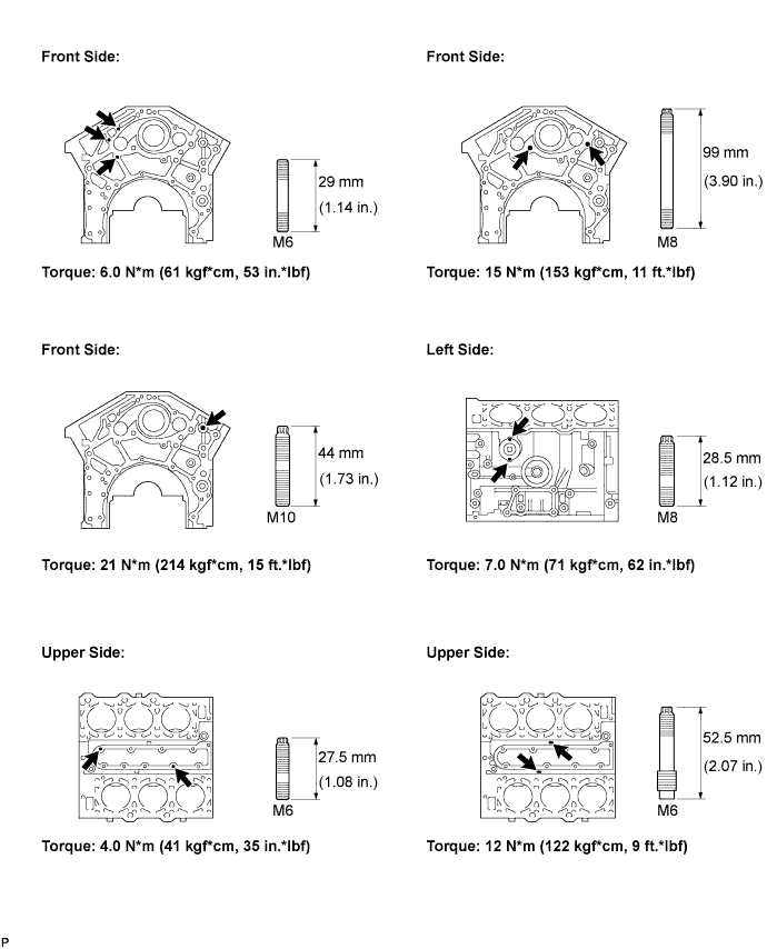
| 1. INSTALL STUD BOLT |


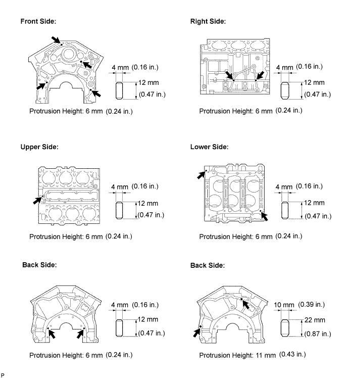
| 2. INSTALL STRAIGHT PIN |
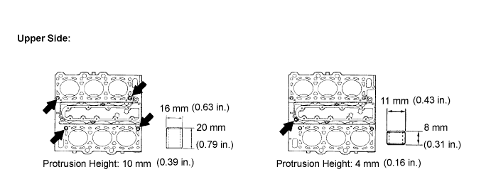
| 3. INSTALL RING PIN |
| 4. INSTALL PISTON PIN HOLE SNAP RING |
Using a screwdriver, install a new snap ring at one end of the piston pin hole.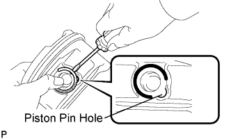
- HINT:
- Be sure that end gap of the snap ring is not aligned with the pin hole cutout portion of the piston.
| 5. INSTALL W/ PIN PISTON SUB-ASSEMBLY |
Gradually heat the piston to about 80°C (176°F).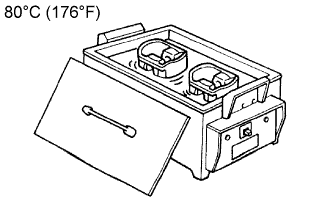
Coat the piston pin with engine oil.
Align the front marks of the piston and connecting rod, and push in the piston pin with your thumb until the pin contacts the snap ring.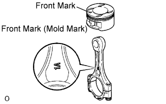
| 6. INSTALL PISTON PIN HOLE SNAP RING |
Using a screwdriver, install a new snap ring on the other end of the piston pin hole.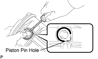
- HINT:
- Be sure that end gap of the snap ring is not aligned with the pin hole cutout portion of the piston.
| 7. INSTALL PISTON RING SET |
Install the oil ring expander by hand.
Using a piston ring expander, install the oil ring side rail.
Using a piston ring expander, install the 2 compression rings.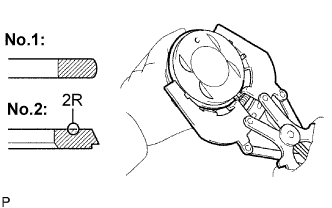
- HINT:
- The compression ring No.2 is installed with code mark "2R" facing upward as shown in the illustration.
Position the piston rings so that the ring ends are arranged as shown in the illustration.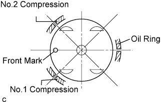
- NOTICE:
- Do not align the ring ends.
| 8. INSTALL CONNECTING ROD BEARING |
Align the key of the bearing with the keyway of the connecting rod or connecting cap.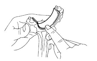
- NOTICE:
- Clean the backside of the bearing and the bearing surface of the connecting rod. The surface should be free of dust and oils.
| 9. INSTALL CRANKSHAFT BEARING |
Clean each main journal and the bearing.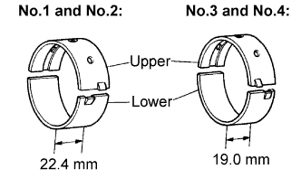
- HINT:
- Main bearings come in widths of 22.4 mm (0.882 in.) and 19.0 mm (0.748 in.). Install the 22.4 mm (0.882 in.) bearings in the No.1 and No.2 cylinder block journal positions with the main bearing cap. Install the 19.0 mm (0.748 in.) bearings in the No.3 and No.4 positions.
Align the key of the bearing with the keyway of the cylinder block, and push in the 4 upper bearings.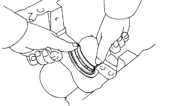
- NOTICE:
- Do not apply engine oil to the bearing and its contact surface.
Align the key of the bearing with the keyway of the main bearing cap, and push in the 4 lower bearings.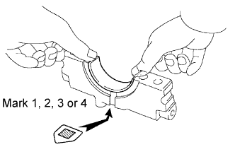
- NOTICE:
- Do not apply engine oil to the bearing and its contact surface.
- HINT:
- A number is marked on each main bearing cap to indicate the installation position.
| 10. INSTALL CRANKSHAFT THRUST WASHER SET |
Install the 2 thrust washers under the No.2 journal position of the cylinder block with the oil grooves facing outward.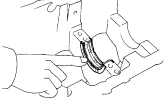
Install the 2 thrust washers on the No.2 bearing cap with the grooves facing outward.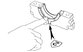
| 11. INSTALL CRANKSHAFT |
Apply engine oil to upper bearing and install the crankshaft on the cylinder block.
Examine the front marks and numbers and install the bearing caps on the cylinder block.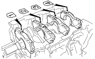
Apply a light coat of engine oil to the threads of the bearing cap bolts.
Temporarily install the 8 main bearing cap bolts to the inside positions.
Install the main bearing cap by hand until clearance between the cylinder block and the bearing cap becomes 6 mm (0.23 in.) or less.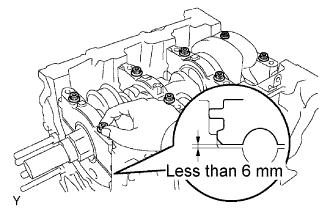
Using a plastic-faced hammer, lightly tap the bearing cap to ensure a proper fit.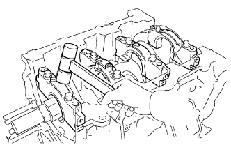
Apply a light coat of engine oil to the threads of the main bearing cap bolts.
Using several steps, install and tighten the 16 main bearing cap bolts uniformly in the sequence shown in the illustration.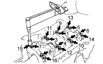
- Torque:
- 22 N*m{ 224 kgf*cm , 16 ft.*lbf }
Mark the front side of the bearing cap bolts with paint.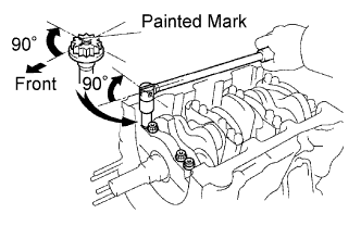
Retighten the bearing cap bolts by 90° in the same sequence as step (h).
Check that each painted mark is now at 90° angle to the front.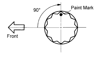
Check that the crankshaft turns smoothly.
Using several steps, install and tighten the 8 main bearing cap bolts and 8 new seal washers uniformly in the sequence shown in the illustration.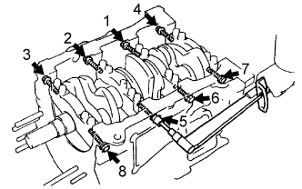
- Torque:
- 27 N*m{ 275 kgf*cm , 20 ft.*lbf }
- HINT:
- Use the short bolt for the marked position (arrow).
| 12. INSTALL PISTON SUB-ASSEMBLY W/ CONNECTING ROD |
Apply engine oil to the cylinder walls, the pistons, and the surfaces of the connecting rod bearings.
Check the position of the piston ring ends.
Using a piston ring compressor, push the correctly numbered piston and connecting rod assemblies into each cylinder with the front mark of the piston facing forward.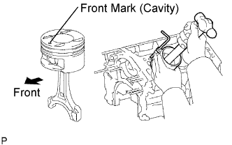
- NOTICE:
- Match the numbered connecting rod cap with the connecting rod.
Check that the protrusion of the connecting rod cap is facing the correct direction.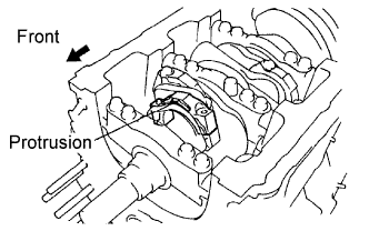
Apply a light coat of engine oil to the threads of the connecting rod cap bolts.
Tighten the bolts in several steps to the specified torque.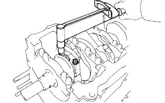
- Torque:
- 25 N*m{ 255 kgf*cm , 18 ft.*lbf }
Mark the front side of each connecting cap bolt with paint.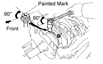
Retighten the cap bolts by 90° as shown in the illustration.
Check that the crankshaft turns smoothly.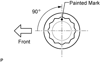
| 13. INSTALL CYLINDER BLOCK W/ HEAD STRAIGHT SCREW NO.3 PLUG |
Using a socket hexagon wrench 10 mm, install a new gasket and the screw plug.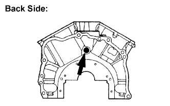
- Torque:
- 50 N*m{ 510 kgf*cm , 37 ft.*lbf }
| 14. INSTALL CYLINDER BLOCK W/ HEAD STRAIGHT SCREW NO.2 PLUG |
Using a socket hexagon wrench 10 mm, install a new gasket and the screw plug.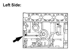
- Torque:
- 30 N*m{ 306 kgf*cm , 22 ft.*lbf }
| 15. INSTALL CYLINDER BLOCK W/ HEAD STRAIGHT SCREW NO.1 PLUG |
Using a socket hexagon wrench 10 mm, install a new gasket and the screw plug.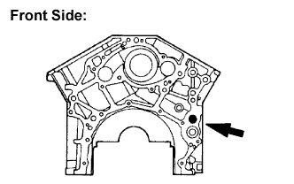
- Torque:
- 50 N*m{ 510 kgf*cm , 37 ft.*lbf }
| 16. INSTALL WATER SEAL PLATE |
Remove any old seal packing from the contact surface.
Apply a continuous bead of seal packing (Diameter 4 to 5 mm (0.16 to 0.20 in.) as shown in the illustration.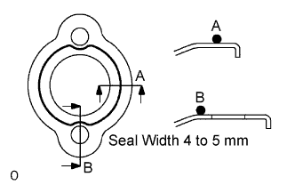
- Seal packing:
- Part No.08826-00100 or equivalent
- NOTICE:
- Remove any oil from the contact surface.
- Install the seal plate within 3 minutes after applying seal packing.
- Do not expose the seal to engine oil within 2 hours after installing.
- Remove any oil from the contact surface.
Install the seal plate with the 2 nuts.
- Torque:
- 18 N*m{ 184 kgf*cm , 13 ft.*lbf }
| 17. INSTALL CYLINDER BLOCK WATER DRAIN COCK SUB-ASSEMBLY |
Apply adhesive to 2 or 3 threads of the drain cock end.
- Adhesive:
- Part No.08833-00070, THREE BOND 1324 or equivalent
After applying the specified torque, rotate the drain cock clockwise as shown in the illustration.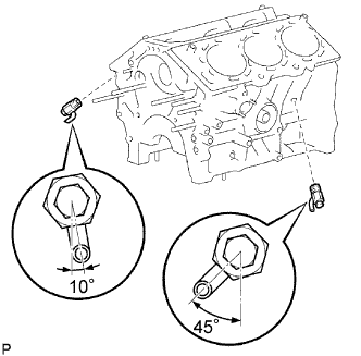
- Torque:
- 39 N*m{ 398 kgf*cm , 29 ft.*lbf }
- NOTICE:
- Install the drain cock within 3 minutes after applying adhesive.
- Do not expose the seal to coolant within 1 hour after installing.
- Do not rotate the drain cock more than 1 revolution (360°) after tightening the drain cock to the specified torque.
- Do not loosen the drain cock after setting it correctly.
- Install the drain cock within 3 minutes after applying adhesive.
| 18. INSTALL RING W/ HEAD PIN (RH CYLINDER) (RH CYLINDER) |
Using a plastic-faced hammer, tap in a new ring pin to the specified protrusion height.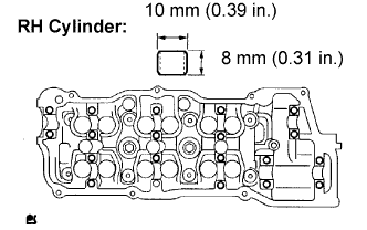
- Protrusion height:
- 3 mm (0.12 in.)
| 19. INSTALL RING PIN (LH CYLINDER) |
Using a plastic-faced hammer, tap in a new ring pin to the specified protrusion height.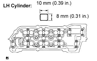
- Protrusion height:
- 3 mm (0.12 in.)
| 20. INSTALL STUD BOLT |
Install the stud bolts on the intake side.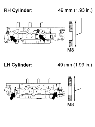
- Torque:
- 8.0 N*m{ 82 kgf*cm , 71 in.*lbf }
| 21. INSTALL STUD BOLT |
Install the stud bolts on the exhaust side.
- Torque:
- 20 N*m{ 204 kgf*cm , 15 ft.*lbf }
| 22. INSTALL VALVE SPRING SEAT |
Install the valve spring seat.
| 23. INSTALL VALVE STEM OIL SEAL OR RING |
Apply a light coat of engine oil to the valve stem.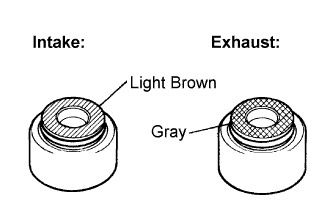
- NOTICE:
- Pay much attention when assembling the oil seal for intake and exhaust. Assembling the wrong one may cause an improper installation.
- HINT:
- The intake valve oil seal is light brown and the exhaust valve oil seal is gray.
Using SST, push in new oil seals.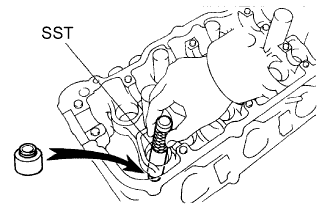
- SST
- 09201-41020
- NOTICE:
- Failure to use SST will cause the seal to be damaged or improperly seated.
| 24. INSTALL INTAKE VALVE |
Install the valve, spring seat, valve spring, and spring retainer.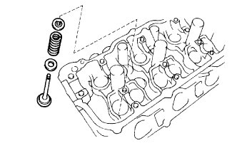
- NOTICE:
- Install the same parts in the same combination to the original locations.
Using SST, compress the valve spring and place the 2 retainer locks around the valve stem.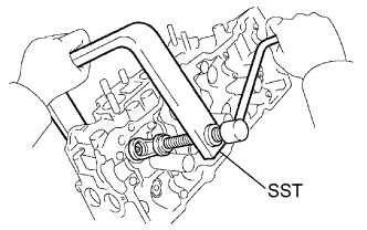
- SST
- 09202-70020
(09202-00010)
Using a plastic-faced hammer and a discarded valve (the tip is wrapped with tape), lightly tap the installed valve to fit into place.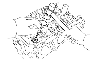
- NOTICE:
- Do not damage the installed valve stem tip.
| 25. INSTALL EXHAUST VALVE |
Install the valve, spring seat, valve spring, and spring retainer.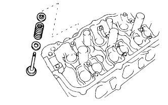
- NOTICE:
- Install the same parts in the same combination to the original locations.
Using SST, compress the valve spring and place the 2 retainer locks around the valve stem.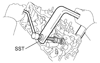
- SST
- 09202-70020
(09202-00010)
Using a plastic hammer and a discarded valve (the tip is wrapped with tape), lightly tap the installed valve to fit into place.
- NOTICE:
- Do not damage the installed valve stem tip.
| 26. INSTALL VALVE LIFTER |
Apply a light coat of engine oil to the valve lifter.
- NOTICE:
- Install the same parts in the same combination to the original locations.
Install the valve lifter.
Check that the valve lifter rotates smoothly by hand.
| 27. INSTALL SEMICIRCULAR PLUG |
Remove any old seal packing (FIPG) material.
Apply seal packing to the semi-circular plug grooves.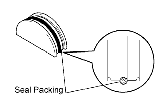
- Seal packing:
- Part No.08826-00080 or equivalent
Install the 2 semi-circular plugs to the cylinder heads.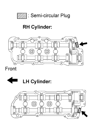
- NOTICE:
- Install the plugs so that it is flush with the top of the cylinder head.
- Install the semi-circular plugs within 3 minutes after applying seal packing.
- Do not expose the seal to engine oil within 2 hours after installing.
- Install the plugs so that it is flush with the top of the cylinder head.
| 28. INSTALL W/ HEAD STRAIGHT SCREW PLUG NO.2 (LH CYLINDER) (LH CYLINDER) |
Using a hexagon wrench 14 mm, install 2 new gaskets and the 2 screw plugs.
- Torque:
- 44 N*m{ 449 kgf*cm , 32 ft.*lbf }
| 29. INSTALL W/ HEAD STRAIGHT SCREW PLUG NO.1 (RH CYLINDER) (RH CYLINDER) |
Using a hexagon wrench 14 mm, install 2 new gaskets and the 2 screw plugs.
- Torque:
- 44 N*m{ 449 kgf*cm , 32 ft.*lbf }
| 30. INSTALL SPARK PLUG TUBE GASKET |
Using SST and a hammer, tap in a new gasket until its surface is flush with the upper edge of the cylinder head cover.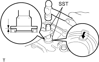
- SST
- 09950-60010
(09951-00430)
09950-70010 (09951-07100)
Return the ventilation plate tab to its original position.
Apply a light coat of MP grease to the gasket lip.
| 31. INSTALL ENGINE REAR OIL SEAL |
Using SST and a hammer, tap in a new oil seal until its surface is flush with the rear oil seal retainer edge.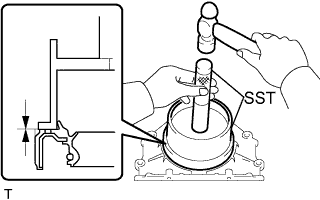
- SST
- 09223-15030
09950-70010 (09951-07100)
- NOTICE:
- Do not tap the oil seal at an angle.
- Keep the lip free of foreign objects.
- Do not tap the oil seal at an angle.
Apply MP grease to the oil seal lip.
| 32. INSTALL ENGINE REAR OIL SEAL RETAINER |
Remove any old packing material from the contact surface.
Apply a continuous bead of seal packing (Diameter 2 to 3 mm (0.08 to 0.12 in.)) as shown in the illustration.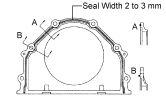
- Seal packing:
- Part No.08826-00080 or equivalent
- NOTICE:
- Remove any oil from the contact surface.
- Install the oil seal retainer within 3 minutes after applying seal packing.
- Do not expose the seal to engine oil within 2 hours after installing.
- Remove any oil from the contact surface.
Install the oil seal retainer with the 6 bolts. Tighten the bolts uniformly in several steps.
- Torque:
- 8.0 N*m{ 82 kgf*cm , 71 in.*lbf }
| 33. INSTALL OIL PUMP SEAL |
Using SST and a hammer, tap in a new oil seal until its surface is flush with the oil pump body edge.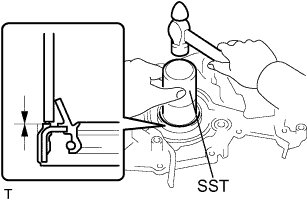
- SST
- 09223-00010
- NOTICE:
- Do not tap the oil seal at an angle.
- Keep the lip free of foreign objects.
- Do not tap the oil seal at an angle.
Apply MP grease to the oil seal lip.
| 34. INSTALL OIL PUMP ASSEMBLY |
Remove any old packing material from the contact surface.
Apply a light coat of engine oil to a new O-ring and place it on the cylinder block.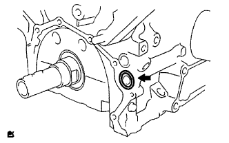
Apply a continuous bead of seal packing (Diameter 2 to 3 mm (0.08 to 0.12 in.)) as shown in the illustration.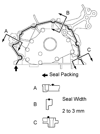
- Seal packing:
- Part No.08826-00080 or equivalent
- NOTICE:
- Remove any oil from contact surface.
- Apply seal packing to the inner side of the bolt holes.
- Install the oil pump within 3 minutes after applying seal packing.
- Do not expose the seal to engine oil within 2 hours after installing.
- Remove any oil from contact surface.
Align the key of the oil pump drive gear with the keyway located on the crankshaft, and slide the oil pump into place.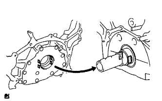
Install the oil pump with the 9 bolts. Tighten the bolts uniformly in several steps.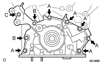
- Torque:
- Bolt A:
- 8.0 N*m{ 82 kgf*cm , 71 in.*lbf }
- Bolt B:
- 20 N*m{ 204 kgf*cm , 15 ft.*lbf }
- Bolt C:
- 43 N*m{ 438 kgf*cm , 32 ft.*lbf }
| 35. INSTALL OIL PAN BAFFLE PLATE |
- Torque:
- 8.0 N*m{ 82 kgf*cm , 71 in.*lbf }
| 36. INSTALL OIL PAN SUB-ASSEMBLY |
Remove any old seal packing from the contact surface.
Apply a continuous bead of seal packing (Diameter 3 to 4 mm (0.12 to 0.16 in.)) as shown in the illustration.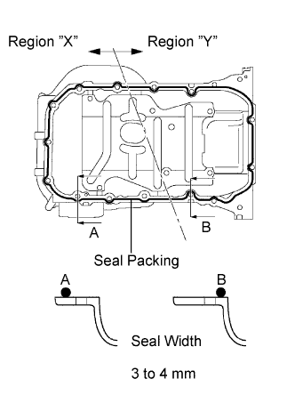
- Seal packing:
- Part No.08826-00080 or equivalent
- NOTICE:
- Remove any oil from the contact surface.
- Apply seal packing to the outer side of the bolt holes in the region "X".
- Apply seal packing to the inner side of the bolt holes in the region "Y".
- Install the oil pan within 3 minutes after applying seal packing.
- Do not expose the seal to engine oil within 2 hours after installing.
- Remove any oil from the contact surface.
Install the oil pan No.1 with the 17 bolts. Tighten the bolts uniformly in several steps.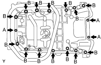
- Torque:
- 10 mm Bolt A:
- 8.0 N*m{ 82 kgf*cm , 71 in.*lbf }
- 12 mm Bolt B:
- 20 N*m{ 204 kgf*cm , 15 ft.*lbf }
| 37. INSTALL OIL STRAINER SUB-ASSEMBLY |
Install a new gasket and the oil strainer with the bolt and 2 nuts.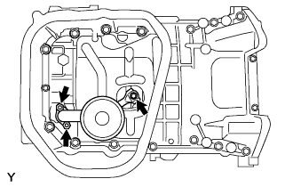
- Torque:
- 8.0 N*m{ 82 kgf*cm , 71 in.*lbf }
| 38. INSTALL OIL PAN SUB-ASSEMBLY NO.2 |
Remove any old seal packing from the contact surface.
Apply a continuous bead of seal packing (Diameter 4 to 5 mm (0.16 to 0.20 in.)) as shown in the illustration.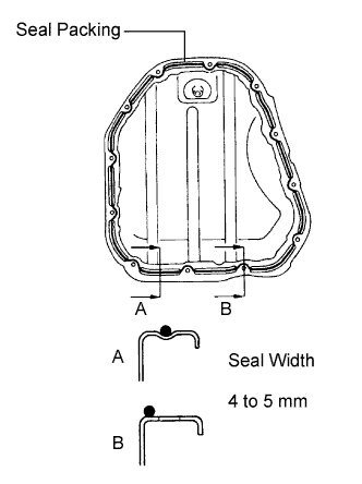
- Seal packing:
- Part No.08826-00080 or equivalent
- NOTICE:
- Remove any oil from the contact surface.
- Apply seal packing to the inner side of the bolt holes.
- Install the oil pan within 3 minutes after applying seal packing.
- Do not expose the seal to engine oil within 2 hours after installing.
- Remove any oil from the contact surface.
Install the oil pan No.2 with the 10 bolts and 2 nuts.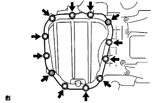
- Torque:
- 8.0 N*m{ 82 kgf*cm , 71 in.*lbf }
| 39. INSTALL OIL PAN DRAIN PLUG |
Install the drain plug with a new gasket.
- Torque:
- 45 N*m{ 459 kgf*cm , 33 ft.*lbf }
| 40. INSTALL OIL FILTER SUB-ASSEMBLY |
Using a socket hexagon wrench 12 mm, install the oil filter union.
- Torque:
- 30 N*m{ 306 kgf*cm , 22 ft.*lbf }
Check and clean the oil filter installation surface.
Apply clean engine oil to the gasket of a new oil filter.
Lightly screw the oil filter into place, and tighten it until the gasket contacts the seat.
Using SST, tighten it an additional 3/4 turn.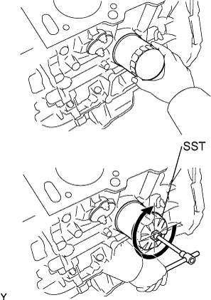
- SST
- 09228-07501
| 41. INSTALL WATER INLET HOUSING |
Remove any old packing material from the contact surface.
Apply a continuous bead of seal packing (Diameter 3 to 5 mm (0.12 to 0.20 in.) as shown in the illustration.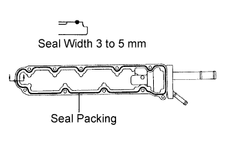
- Seal packing:
- Part No.08826-00100 or equivalent
- NOTICE:
- Remove any oil from the contact surface.
- Install the water inlet housing within 3 minutes after applying seal packing.
- Do not expose the seal to coolant within 2 hours after installing.
- Remove any oil from the contact surface.
Install the water inlet housing with the 8 bolts and 2 nuts. Using several steps, tighten the bolts and nuts uniformly in the sequence shown in the illustration.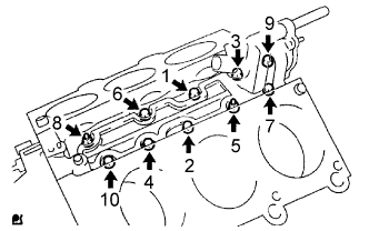
- Torque:
- 8.0 N*m{ 82 kgf*cm , 71 in.*lbf }
| 42. INSTALL CYLINDER HEAD GASKET |
Place a new cylinder head gasket on the cylinder block with the R mark upward.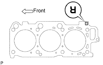
- NOTICE:
- Remove any oil from the contact surface.
- Be careful to install the gasket in the correct direction.
- Place the cylinder head on the gasket carefully in order not to damage the gasket at the bottom part of the head.
- Remove any oil from the contact surface.
| 43. INSTALL CYLINDER HEAD SUB-ASSEMBLY |
Apply a light coat of engine oil to the threads of the cylinder head bolts.
Install the plate washers to the cylinder head bolts.
Using several steps, install and tighten the 8 cylinder head bolts uniformly in the sequence shown in the illustration.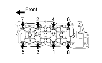
- Torque:
- 54 N*m{ 550 kgf*cm , 40 ft.*lbf }
- NOTICE:
- The cylinder head bolts are tightened in 2 successive steps.
Mark the front side of each cylinder head bolt head with paint as shown in the illustration.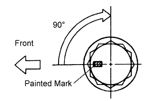
Retighten the cylinder head bolts by 90° in the same sequence as step (c).
Check that each painted mark is now at a 90° angle to the front.
Using a socket hexagon wrench 8 mm, install the hexagon bolt.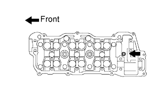
- Torque:
- 19 N*m{ 194 kgf*cm , 14 ft.*lbf }
| 44. INSTALL CYLINDER HEAD GASKET NO.2 |
Place a new cylinder head gasket on the cylinder block with the L mark upward.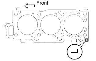
- NOTICE:
- Remove any oil from the contact surface.
- Be careful to install the gasket in the correct direction.
- Place the cylinder head on the gasket carefully in order not to damage the gasket at the bottom part of the head.
- Remove any oil from the contact surface.
| 45. INSTALL CYLINDER HEAD LH |
Apply a light coat of engine oil to the threads of the cylinder head bolts.
Install the plate washers to the cylinder head bolts.
Using several steps, install and tighten the 8 cylinder head bolts uniformly in the sequence shown in the illustration.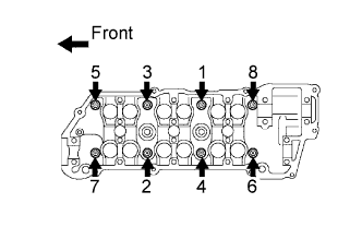
- Torque:
- 54 N*m{ 551 kgf*cm , 40 ft.*lbf }
- NOTICE:
- The cylinder head bolts are tightened in 2 successive steps.
Mark the front side of each cylinder head bolt head with paint as shown in the illustration.
Retighten the cylinder head bolts by 90° in the same sequence as step (c).
Check that each painted mark is now at a 90° angle to the front.
Using a socket hexagon wrench 8 mm, install the hexagon bolt.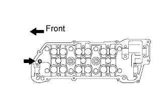
- Torque:
- 19 N*m{ 189 kgf*cm , 14 ft.*lbf }
| 46. INSTALL OIL CONTROL VALVE FILTER |
Check that no foreign object is on the mesh part of the filter.
Assemble the valve filter and the plug.
Install the plug with a new gasket.
- Torque:
- 45 N*m{ 459 kgf*cm , 33 ft.*lbf }
| 47. INSTALL CYLINDER HEAD COVER REAR |
Install the rear cover and a new gasket with the 12 bolts and nut.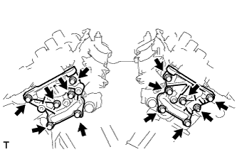
- Torque:
- 10 N*m{ 102 kgf*cm , 7 ft.*lbf }
| 48. INSTALL ENGINE HANGER NO.2 |
Install the 2 bolts and engine hanger No.2.
- Torque:
- 20 N*m{ 214 kgf*cm , 15 ft.*lbf }
| 49. INSTALL CAMSHAFT SUB GEAR |
Clamp the camshaft in a vise on the hexagonal lobe.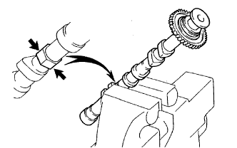
- NOTICE:
- Do not damage the camshaft.
Install the camshaft gear bolt washer and the camshaft sub-gear.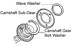
- HINT:
- Attach the pins on the gears to the gear bolt washer ends.
Install the wave washer.
Using snap ring pliers, install the snap ring.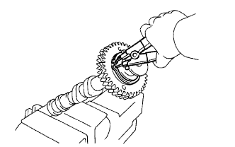
Using SST, align the holes of the camshaft main gear and sub-gear by turning camshaft sub-gear counterclockwise, and temporarily install a service bolt.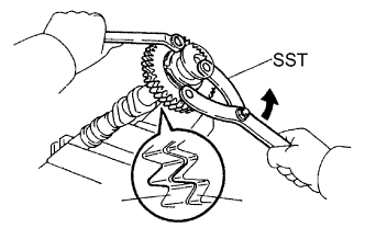
- SST
- 09960-10010
(09962-01000, 09963-00500)
Align the gear teeth of the main gear and sub-gear, and tighten the service bolt.
- Torque:
- 5.0 N*m{ 51 kgf*cm , 44 in.*lbf }
- NOTICE:
- Do not damage the camshaft journals.
- HINT:
- When installing the camshaft, make certain that the torsional spring force of the sub-gear has been eliminated by installing the service bolt.
| 50. INSTALL CAMSHAFT TIMING GEAR ASSEMBLY |
Align the alignment pin with the groove and install VVT-i on the camshaft.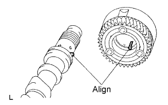
- NOTICE:
- Install it with the lock-pin engaged and locked at the most retard angle position.
Apply engine oil to the nut, the mounting surface of VVT-i and the screw threads.
- NOTICE:
- Be sure to apply the oil, otherwise the specified torque cannot be obtained.
- New nuts must be used when replacing the VVT-i unit.
- Be sure to apply the oil, otherwise the specified torque cannot be obtained.
Using a 46 mm socket wrench, install and tighten a lock nut by turning it counterclockwise.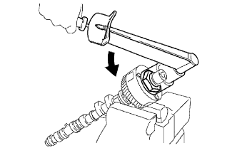
- Torque:
- 150 N*m{ 1,530 kgf*cm , 111 ft.*lbf }
- NOTICE:
- The lock nut has left-hand threads.
- Never use any tool other than the socket wrench. Other tools will deform the cam angle rotor.
- The lock nut has left-hand threads.
| 51. INSTALL NO.2 CAMSHAFT |
- NOTICE:
- Since the thrust clearance of the camshaft is small, the camshaft must be kept level while it is being installed. If the camshaft is not kept level, damage to the cylinder head or to the camshaft may result. To avoid this, the following steps should be carried out.
Apply new engine oil to the thrust portion and journal of the camshaft.
Place the No.2 camshaft at a 90° angle of the timing mark (2-dot mark) on the cylinder head.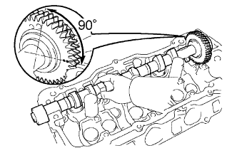
Apply MP grease to a new oil seal lip.
Install the oil seal to the camshaft.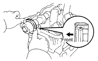
- NOTICE:
- Do not turn over the oil seal lip.
- Insert the oil seal until it stops.
- Do not turn over the oil seal lip.
Remove any old packing material from the contact surface.
Apply seal packing to the No.1 bearing cap as shown in the illustration.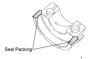
- Seal packing:
- Part No.08826-00080 or equivalent
- NOTICE:
- Install the No.1 bearing cap within 5 minutes after applying seal packing.
- Do not expose the seal to engine oil within 2 hours after installing.
- Install the No.1 bearing cap within 5 minutes after applying seal packing.
Install the 5 bearing caps in their proper locations.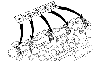
Apply a light coat of engine oil to the threads of the bearing cap bolts.
Using several steps, tighten the 10 bearing cap bolts uniformly in the sequence shown in the illustration.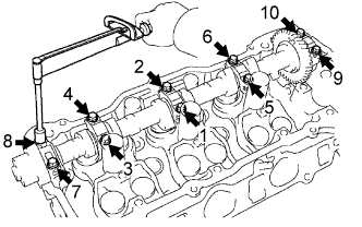
- Torque:
- 16 N*m{ 163 kgf*cm , 12 ft.*lbf }
| 52. INSTALL CAMSHAFT |
- NOTICE:
- Since the thrust clearance of the camshaft is small, the camshaft must be kept level while it is being installed. If the camshaft is not kept level, damage to the cylinder head or to the camshaft may result. To avoid this, the following steps should be carried out.
Apply new engine oil to the thrust portion and journal of the camshaft.
Align the timing marks (2-dot mark) of the camshaft drive gear with the mark on the driven gear.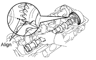
Place the camshaft on the cylinder head.
Install the 5 bearing caps in their proper locations.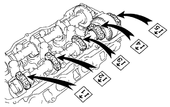
Apply a light coat of engine oil to the threads of the bearing cap bolts.
Using several steps, tighten the 10 bearing cap bolts uniformly in the sequence shown in the illustration.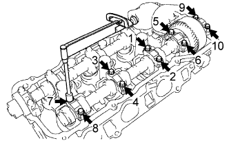
- Torque:
- 16 N*m{ 163 kgf*cm , 12 ft.*lbf }
Remove the service bolt.
| 53. INSTALL NO.4 CAMSHAFT SUB-ASSEMBLY |
- NOTICE:
- Since the thrust clearance of the camshaft is small, the camshaft must be kept level while it is being installed. If the camshaft is not kept level, damage to the cylinder head or to the camshaft may result. To avoid this, the following steps should be carried out.
Apply new engine oil to the thrust portion and journal of the camshaft.
Place the No.4 camshaft at a 90° angle of the timing mark (1-dot mark) on the cylinder head.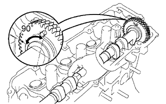
Apply MP grease to a new oil seal lip.
Install the oil seal to the camshaft.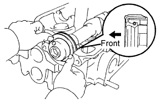
- NOTICE:
- Do not turn over the oil seal lip.
- Insert the oil seal until it stops.
- Do not turn over the oil seal lip.
Remove any old packing material from the contact surface.
Apply seal packing to the No.1 bearing cap as shown in the illustration.
- Seal packing:
- Part No.08826-00080 or equivalent
- NOTICE:
- Install the No.1 bearing cap within 5 minutes after applying seal packing.
- Do not expose the seal to engine oil within 2 hours after installing.
- Install the No.1 bearing cap within 5 minutes after applying seal packing.
Install the 5 bearing caps in their proper locations.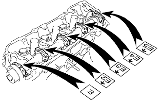
Apply a light coat of engine oil to the threads of the bearing cap bolts.
Using several steps, tighten the 10 bearing cap bolts uniformly in the sequence shown in the illustration.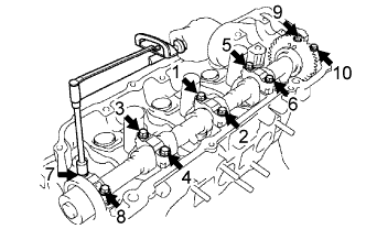
- Torque:
- 16 N*m{ 163 kgf*cm , 12 ft.*lbf }
| 54. INSTALL NO.3 CAMSHAFT SUB-ASSEMBLY |
- NOTICE:
- Since the thrust clearance of the camshaft is small, the camshaft must be kept level while it is being installed. If the camshaft is not kept level, damage to the cylinder head or to the camshaft may result. To avoid this, the following steps should be carried out.
Apply new engine oil to the thrust portion and journal of the camshaft.
Align the timing marks (1-dot mark) of the camshaft drive gear with the mark on the driven gear.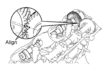
Place the camshaft on the cylinder head.
Install the 5 bearing caps in their proper locations.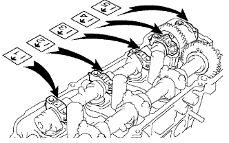
Apply a light coat of engine oil to the threads of the bearing cap bolts.
Using several steps, tighten the 10 bearing cap bolts uniformly in the sequence shown in the illustration.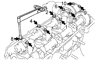
- Torque:
- 16 N*m{ 163 kgf*cm , 12 ft.*lbf }
Remove the service bolt.
| 55. INSTALL WATER PUMP ASSEMBLY |
Install a new gasket and the water pump with the 3 bolts and 3 nuts.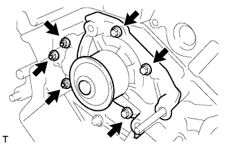
- Torque:
- 8.0 N*m{ 82 kgf*cm , 71 in.*lbf }
| 56. INSTALL CRANKSHAFT TIMING PULLEY |
Align the keyway of the timing pulley with the key located on the crankshaft and slide the timing pulley into place.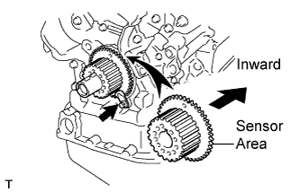
- NOTICE:
- Do not scratch the sensor area of the crankshaft timing pulley.
Install the timing belt plate with the bolt.
- Torque:
- 8.0 N*m{ 82 kgf*cm , 71 in.*lbf }
| 57. INSTALL OIL LEVEL GAGE GUIDE |
Apply a light coat of engine oil to a new O-ring and install it to the level gage guide.
Install the level gage guide.
- Torque:
- 8.0 N*m{ 82 kgf*cm , 71 in.*lbf }
| 58. INSTALL OIL LEVEL GAGE SUB-ASSEMBLY |
Install the oil level gage sub-assembly.
| 59. INSTALL TIMING BELT IDLER BRACKET |
- Torque:
- 28 N*m{ 286 kgf*cm , 21 ft.*lbf }
| 60. INSTALL TIMING BELT NO.3 COVER |
Visually check for cracks and breaks on the gasket of the timing belt cover.
- HINT:
- If a trace of water is found in the visual check, repair it with seal packing when the crack length is within 2 to 3 cm (0.79 to 1.18 in.). Replace the gasket when the crack length is 3 to 4 cm (1.18 to 1.57 in.) and more.
If the timing belt cover gasket is needed to repair, follow the procedure below.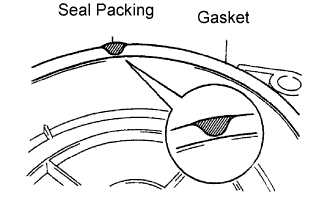
Repair the cracks and breaks by applying the seal packing to the damaged area.
- Seal packing:
- Part No.08826-00080 or equivalent
- NOTICE:
- When applying the seal packing, apply it as wide and high as possible to fill the surface area of the gasket.
If the timing belt cover gasket is needed to replace, follow the procedure below.
Using a screwdriver and gasket scraper, remove the remaining gasket.
- NOTICE:
- Do not damage the timing belt cover.
Remove the backing paper from a new gasket, and affix the gasket along the groove of the timing belt cover as shown in the illustration.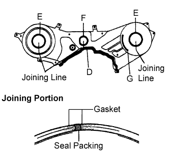
- NOTICE:
- Affix the gasket in the center of the groove.
- At the corners, try to keep the gasket thickness uniform.
- Affix the gasket in the center of the groove.
Gasket
D
E
F
G
Length
335 mm
(13.19 in.)
180 mm
(7.09 in.)
133 mm
(5.24 in.)
72 mm
(2.83 in.)
If there is a gap on the joint of the gasket, apply seal packing to close the gap.
- Seal packing:
- Part No.08826-00080 or equivalent
- NOTICE:
- When applying the seal packing, apply it as wide and high as possible to fill the surface area of the gasket.
Install the timing belt cover with the 6 bolts.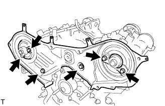
- Torque:
- 9.0 N*m{ 92 kgf*cm , 80 in.*lbf }
| 61. INSTALL CAMSHAFT TIMING PULLEY |
Paying attention to the direction of the belt guide, install the camshaft timing pulley and tighten the bolt temporally.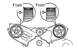
- HINT:
- Face the belt guide of the RH timing pulley toward front of the engine.
- Face the belt guide of the LH timing pulley toward rear of the engine.
- Face the belt guide of the RH timing pulley toward front of the engine.
Using SST, tighten the RH pulley bolt.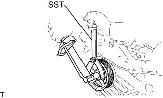
- SST
- 09960-10010
(09962-01000, 09963-01000)
- Torque:
- 125 N*m{ 1,275 kgf*cm , 92 ft.*lbf }
Using SST, tighten the LH pulley bolt.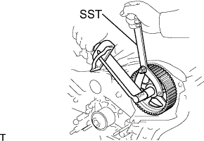
- SST
- 09960-10010
(09962-01000, 09963-01000)
- Torque:
- 125 N*m{ 1,275 kgf*cm , 92 ft.*lbf }
| 62. INSTALL CRANKSHAFT POSITION SENSOR |
Install the crankshaft position sensor with the bolt.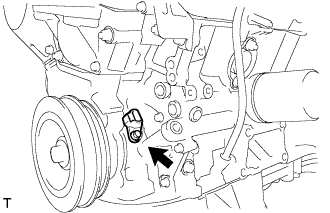
- Torque:
- 8.0 N*m{ 82 kgf*cm , 71 in.*lbf }
| 63. INSTALL TIMING BELT IDLER SUB-ASSEMBLY NO.2 |
- Torque:
- 43 N*m{ 438 kgf*cm , 32 ft.*lbf }
| 64. INSTALL TIMING BELT IDLER SUB-ASSEMBLY NO.1 |
Using a socket hexagon wrench 10 mm, install the plate washer and timing belt idler No.1 with the pivot bolt.
- Torque:
- 34 N*m{ 347 kgf*cm , 25 ft.*lbf }
| 65. INSTALL TIMING BELT |
Remove any oil or water on the pulleys, and keep them clean.
- NOTICE:
- If there is a trace of water and/or oil on the timing belt, repair the leakage and install a new timing belt.
- Wipe only the pulleys; do not use any cleaning agent.
- If there is a trace of water and/or oil on the timing belt, repair the leakage and install a new timing belt.
Inspect the idler pulleys.
Check that the idler pulley turns smoothly.
Visually check the seal portion of the idler pulley for oil leakage.
Inspect the water pump.
Turn the pulley, and check that the water pump bearing moves smoothly and does not make any noise.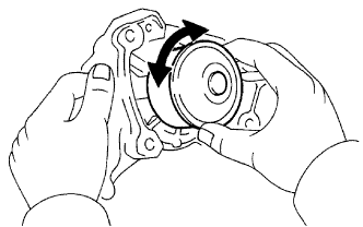
Visually check the drain hole for coolant leakage.
Temporarily install the crankshaft pulley bolt and washer to the crankshaft.
Turn the crankshaft counterclockwise by approximately 60°.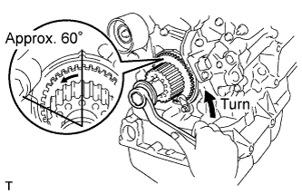
- NOTICE:
- To prevent contacting the piston head and the valve head, set the crankshaft pulley at 60° BTDC/compression position.
Using SST, turn the crankshaft pulley, and align the timing marks of the timing pulley with the No.3 timing belt cover.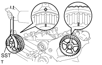
- SST
- 09960-10010
(09962-01000, 09963-01000)
Turn the crankshaft, and align the timing marks of the crankshaft timing pulley with the oil pump body.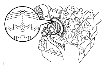
Face the front mark on the timing belt forward.
Align the installation mark on the timing belt with the timing mark of the crankshaft timing pulley.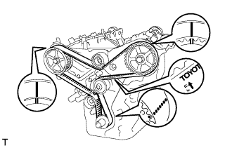
Align the installation marks on the timing belt with the timing marks of the camshaft timing pulleys.
Install the timing belt in the following order.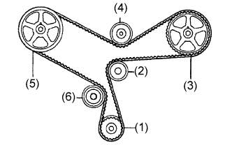
1st
Crankshaft timing pulley
2nd
Water pump pulley
3rd
LH camshaft timing pulley
4th
No.2 idler pulley
5th
RH camshaft timing pulley
6th
No.1 idler pulley
| 66. INSTALL CHAIN TENSIONER ASSEMBLY NO.1 |
Set the timing belt tensioner upright on the press.
Slowly press in the push rod.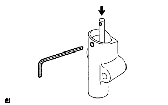
- NOTICE:
- Do not apply pressure more than 9.8 kN (1,000 kgf, 2,205 lbf) to the rod.
Align the holes of the push rod and housing, pass a 1.5 mm hexagon wrench through the holes to keep the setting position of the push rod.
Release the press.
Temporarily install the tensioner with the 2 bolts. Alternately tighten the 2 bolts.
- Torque:
- 27 N*m{ 275 kgf*cm , 20 ft.*lbf }
- NOTICE:
- Be sure to tighten the bolts equally. Installing the tensioner at an angle may cause improper operation.
Remove the 1.5 mm hexagon wrench from the tensioner.
Turn the crankshaft 2 revolutions slowly, and align the timing mark of the crankshaft timing pulley with the oil pump body.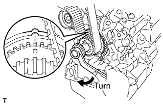
- NOTICE:
- Always turn the crankshaft clockwise.
Check the timing marks of the RH and LH timing pulleys are aligned with the timing marks of the No.3 timing belt cover as shown in the illustration.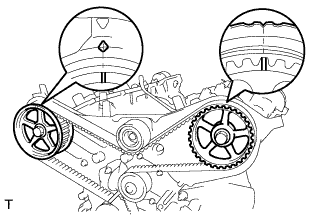
- HINT:
- If the marks do not align, remove the timing belt and reinstall it.
Remove the crankshaft pulley bolt.
| 67. INSTALL TIMING BELT GUIDE NO.2 |
Install the timing belt guide with the cup side facing toward the engine front.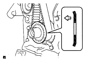
| 68. INSTALL ENGINE MOUNTING BRACKET RH |
Install the 2 bolts, 2 nuts and engine mounting bracket RH.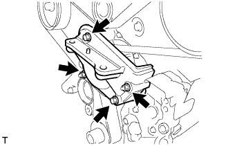
- Torque:
- 28 N*m{ 286 kgf*cm , 21 ft.*lbf }
| 69. INSTALL TIMING BELT NO.2 COVER |
Visually check for cracks and breaks on the gasket of the timing belt cover.
If a trace of water is found in the visual check, replace the timing belt cover.
Install the timing belt cover.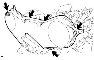
- Torque:
- 9.0 N*m{ 92 kgf*cm , 80 in.*lbf }
| 70. INSTALL TIMING BELT NO.1 COVER |
Visually check for cracks and breaks on the gasket of the timing belt cover.
If a trace of water is found in the visual check, replace the timing belt cover.
Install the timing belt cover.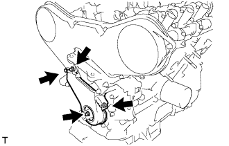
- Torque:
- 9.0 N*m{ 92 kgf*cm , 80 in.*lbf }
| 71. INSTALL CRANKSHAFT PULLEY |
Align the keyway of the pulley with the key located on the crankshaft and slide the pulley into place.
Using SST, install the pulley bolt.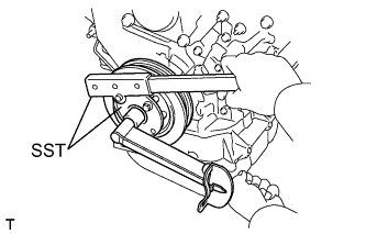
- SST
- 09213-54015
(91651-60855)
09330-00021
- Torque:
- 220 N*m{ 2,243 kgf*cm , 162 ft.*lbf }
| 72. INSTALL ENGINE OIL LEVEL SENSOR |
Install the engine oil level sensor and a new gasket with the 4 bolts.
- Torque:
- 8.5 N*m{ 87 kgf*cm , 75 in.*lbf }
| 73. INSTALL VVT SENSOR |
Install the 2 VVT sensors.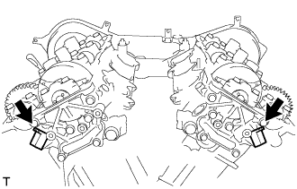
- Torque:
- 8.0 N*m{ 82 kgf*cm , 71 in.*lbf }
| 74. INSTALL CAMSHAFT TIMING OIL CONTROL VALVE ASSEMBLY |
Install the 2 new O-rings and 2 camshaft timing oil control valves.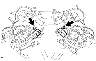
- Torque:
- 8.0 N*m{ 82 kgf*cm , 71 in.*lbf }
| 75. INSPECT VALVE CLEARANCE |
Turn the crankshaft pulley, and align the timing notch with the timing mark "0" of the No.1 timing belt cover.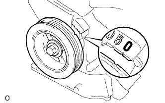
Check that the valve lifters on the No.1 cylinder (IN and EX) are both loose.
If not, turn the crankshaft 1 revolution (360°) and align the mark as above.
Check the valves indicated in the illustration.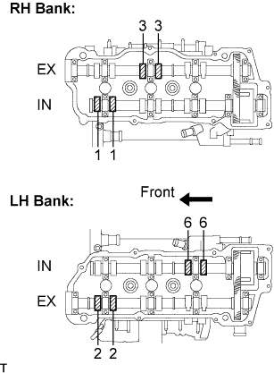
Using a feeler gauge, measure the clearance between the valve lifter and the camshaft.
- Valve clearance (Cold):
- Intake:
- 0.15 to 0.25 mm (0.0059 to 0.0098 in.)
- Exhaust:
- 0.25 to 0.35 mm (0.0098 to 0.0138 in.)
Record out-of-specification valve clearance measurements. They will be used later to determine the required replacement adjusting shim.
Turn the crankshaft 2/3 of a revolution (240°), and check the valves indicated in the illustration.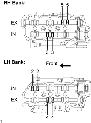
Using a feeler gauge, measure the clearance between the valve lifter and the camshaft.
- Valve clearance (Cold):
- Intake:
- 0.15 to 0.25 mm (0.0059 to 0.0098 in.)
- Exhaust:
- 0.25 to 0.35 mm (0.0098 to 0.0138 in.)
Record out-of-specification valve clearance measurements. They will be used later to determine the required replacement adjusting shim.
Turn the crankshaft 2/3 of a revolution (240°), and check the valves indicated in the illustration.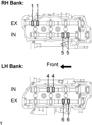
Using a feeler gauge, measure the clearance between the valve lifter and the camshaft.
- Valve clearance (Cold):
- Intake:
- 0.15 to 0.25 mm (0.0059 to 0.0098 in.)
- Exhaust:
- 0.25 to 0.35 mm (0.0098 to 0.0138 in.)
Record out-of-specification valve clearance measurements. They will be used later to determine the required replacement adjusting shim.
| 76. ADJUST VALVE CLEARANCE |
Turn the camshaft so that the cam lobe faces upward.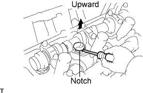
Turn the valve lifter with a screwdriver so that the notches are perpendicular to the camshaft.
Using SST (A), press down the valve lifter and place SST (B) between the camshaft and valve lifter. Remove SST (A).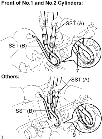
- SST
- 09248-55040
(09248-05410, 09248-05420)
- HINT:
- Apply SST (B) at a slight angle on the side marked with "9" or "7" at the position shown in the illustration.
- When SST (B) is inserted too deeply, it will get pinched by the shim. To prevent it from being stuck, insert it gently from the intake side at a slight angle.
- Apply SST (B) at a slight angle on the side marked with "9" or "7" at the position shown in the illustration.
SST A
09248-05410
SST B
09248-05420
Using a screwdriver and magnetic finger, remove the adjusting shim.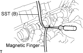
Using a micrometer, measure the thickness of the removed shim.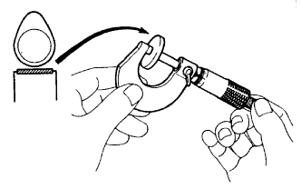
Calculate the thickness of a new shim so the valve clearance comes within the specified value.
A
Thickness of new shim
B
Thickness of used shim
C
Measured valve clearance
- Specified value (Cold):
- Intake A = B + (C - 0.20 mm (0.0079 in.))
- Exhaust A = B + (C - 0.30 mm (0.0118 in.))
Select a new shim with a thickness as close as possible to the calculated values.
EXAMPLE (Intake):
Measured valve clearance = 0.45 mm (0.0177 in.)
0.45 mm (0.0177 in.) - 0.20 mm (0.0079 in.) = 0.25 mm (0.0098 in.)
(Measured - Specification = Excess clearance)
Used shim measurement = 2.80 mm (0.1102 in.)
0.25 mm (0.0098 in.) + 2.80 mm (0.1102 in.) = 3.05 mm (0.1201 in.)
(Excess clearance + Used shim = Ideal new shim)
Closest new shim = 3.05 mm (0.1201 in.)
Select No.12 shim
- HINT:
- Shims are available in 17 sizes in increments of 0.05 mm (0.0020 in.), from 2.50 mm (0.0984 in.) to 3.30 mm (0.1299 in.).
- Refer to new shim thickness table below.
- Shims are available in 17 sizes in increments of 0.05 mm (0.0020 in.), from 2.50 mm (0.0984 in.) to 3.30 mm (0.1299 in.).
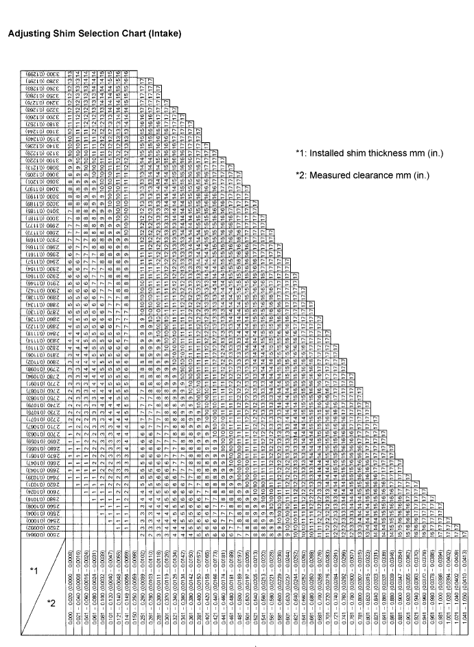
- Intake valve clearance (Cold):
- 0.15 to 0.25 mm (0.0059 to 0.0098 in.)
The 2.800 mm (0.1102 in.) shim is installed, and the measured clearance is 0.450 mm (0.0177 in.).
Replace the 2.800 mm (0.1102 in.) shim with a new No.12 shim.New shim thickness mm (in.) Shim No.
Thickness
Shim No.
Thickness
1
2.500 (0.0984)
10
2.950 (0.1161)
2
2.550 (0.1004)
11
3.000 (0.1181)
3
2.600 (0.1024)
12
3.050 (0.1201)
4
2.650 (0.1043)
13
3.100 (0.1220)
5
2.700 (0.1063)
14
3.150 (0.1240)
6
2.750 (0.1083)
15
3.200 (0.1260)
7
2.800 (0.1102)
16
3.250 (0.1280)
8
2.850 (0.1122)
17
3.300 (0.1299)
9
2.900 (0.1142)
-
-
- HINT:
- New shims have the thickness in millimeters imprinted on the face.
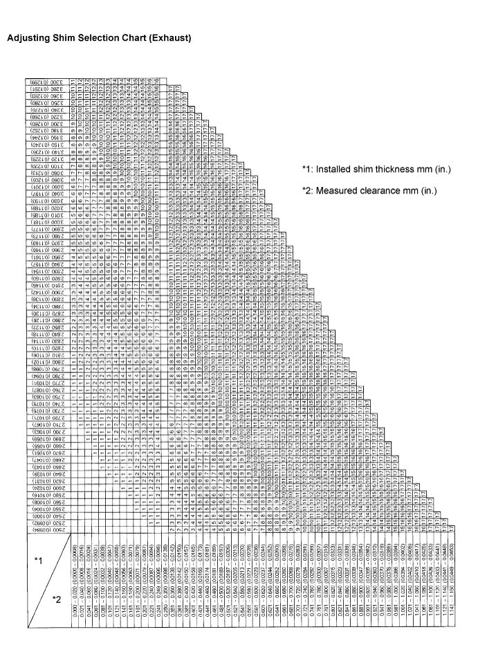
- Exhaust valve clearance (Cold):
- 0.25 to 0.35 mm (0.0098 to 0.0138 in.)
The 2.800 mm (0.1102 in.) shim is installed, and the measured clearance is 0.450 mm (0.0177 in.).
Replace the 2.800 mm (0.1102 in.) shim with a new No.10 shim.New shim thickness mm (in.) Shim No.
Thickness
Shim No.
Thickness
1
2.500 (0.0984)
10
2.950 (0.1161)
2
2.550 (0.1004)
11
3.000 (0.1181)
3
2.600 (0.1024)
12
3.050 (0.1201)
4
2.650 (0.1043)
13
3.100 (0.1220)
5
2.700 (0.1063)
14
3.150 (0.1240)
6
2.750 (0.1083)
15
3.200 (0.1260)
7
2.800 (0.1102)
16
3.250 (0.1280)
8
2.850 (0.1122)
17
3.300 (0.1299)
9
2.900 (0.1142)
-
-
- HINT:
- New shims have the thickness in millimeters imprinted on the face.
Place a new adjusting shim on the valve lifter with imprinted number facing down.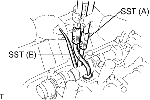
Press down the valve lifter with SST (A), and remove SST (B).
- SST
- 09248-55040
(09248-05410, 09248-05420)
Recheck the valve clearance.
| 77. INSTALL CYLINDER HEAD COVER GASKET NO.2 |
Install the cylinder head cover gasket No.2 to the cylinder head cover sub-assembly LH.
| 78. INSTALL CYLINDER HEAD COVER SUB-ASSEMBLY LH |
Apply seal packing to the cylinder head as shown in the illustration.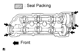
- Seal packing:
- Part No.08826-00080 or equivalent
- NOTICE:
- Remove any oil from the contact surface.
- Install the cylinder head cover within 3 minutes after applying seal packing.
- Do not start the engine within 2 hours after installing.
- Remove any oil from the contact surface.
Install the cylinder head cover with the 9 bolts. Tighten the bolts uniformly in several steps.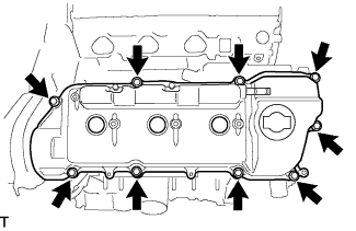
- Torque:
- 12 N*m{ 122 kgf*cm , 9 ft.*lbf }
| 79. INSTALL CYLINDER HEAD COVER GASKET |
Install the cylinder head cover gasket to the cylinder head cover sub-assembly.
| 80. INSTALL CYLINDER HEAD COVER SUB-ASSEMBLY |
Apply seal packing to the cylinder head as shown in the illustration.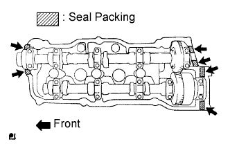
- Seal packing:
- Part No.08826-00080 or equivalent
- NOTICE:
- Remove any oil from the contact surface.
- Install the cylinder head cover within 3 minutes after applying seal packing.
- Do not start the engine within 2 hours after installing.
- Remove any oil from the contact surface.
Install the cylinder head cover with the 9 bolts. Tighten the bolts uniformly in several steps.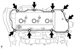
- Torque:
- 12 N*m{ 122 kgf*cm , 9 ft.*lbf }
| 81. INSTALL OIL FILLER CAP GASKET |
Install the oil filler cap gasket to the oil filler cap sub-assembly.
| 82. INSTALL OIL FILLER CAP SUB-ASSEMBLY |
Install the oil filler cap sub-assembly to the cylinder head cover sub-assembly LH.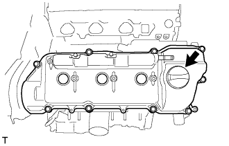
| 83. INSTALL VENTILATION VALVE SUB-ASSEMBLY |
Install the ventilation valve sub-assembly to the cylinder head cover sub-assembly.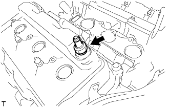
- Torque:
- 27 N*m{ 275 kgf*cm , 20 ft.*lbf }
| 84. INSTALL SPARK PLUG |
Install the spark plug.
- Torque:
- 25 N*m{ 255 kgf*cm , 18 ft.*lbf }