REMOVAL
Removal / installation
| 1. PRECAUTION |

| 2. REMOVE ENGINE ROOM SIDE LH COVER |
Using a clip remover, remove the engine room side cover.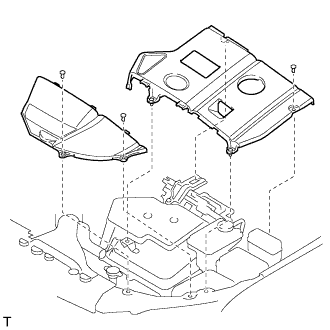

| 3. REMOVE ENGINE ROOM COVER SIDE |
Remove the 5 clips and engine room cover side.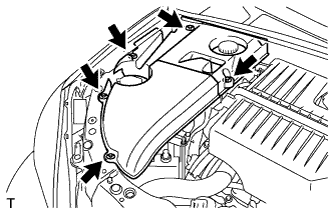
| 4. DISCHARGE FUEL SYSTEM PRESSURE |
| 5. REMOVE SERVICE PLUG GRIP |
- CAUTION:
- Remove the service plug to interrupt a high voltage circuit at the time of the check.
- Keep the removed service plug in your pocket to prevent other technicians from reconnecting it while you are servicing the vehicle.
- All the high voltage wiring connectors are colored in orange.
- Remove the service plug to interrupt a high voltage circuit at the time of the check.
Remove the 2 clips, then open the battery service hole cover.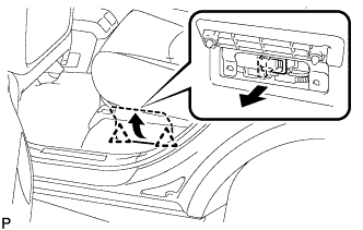
Wear insulation glove, and remove the service plug grip, after sliding up the lever of the service plug grip.
- CAUTION:
- Keep the removed service plug in your pocket to prevent other technicians from reconnecting it while you are servicing the vehicle.
- After removing the service plug grip, do not touch the high voltage connectors and terminals for 5 minutes.
- Keep the removed service plug in your pocket to prevent other technicians from reconnecting it while you are servicing the vehicle.
- NOTICE:
- After removing the service plug grip, do not operate the ignition switch as it may damage the hybrid vehicle control ECU.
| 6. REMOVE FRONT WHEELS |
| 7. REMOVE ENGINE UNDER COVER NO.1 |
Remove the 6 bolts, 2 screws, 2 clips and engine under cover.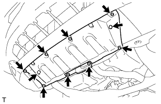
| 8. SEPARATE FRONT FENDER SPLASH SHIELD SUB-ASSEMBLY LH |
Remove the screw and separate the fender splash shield.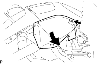
| 9. SEPARATE FRONT FENDER SPLASH SHIELD SUB-ASSEMBLY RH |
- HINT:
- Perform the same procedure as above on the opposite side.
| 10. REMOVE FRONT FENDER APRON SEAL LH |
Remove the 2 bolts, clip and fender apron seal LH.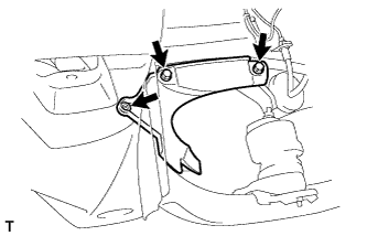
| 11. REMOVE FRONT FENDER APRON SEAL RH |
- HINT:
- Perform the same procedure as above on the opposite side.
| 12. REMOVE ENGINE UNDER COVER NO.2 |
Remove the 2 bolts and engine under cover No.2.
| 13. DRAIN COOLANT (Engine side) |
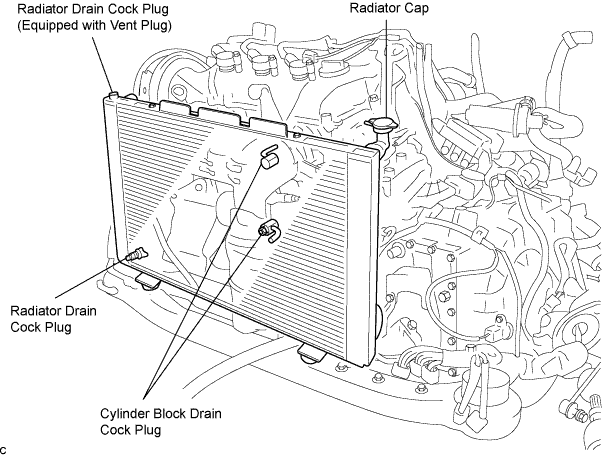
Remove the radiator cap.
- CAUTION:
- To avoid the danger of being burned, do not remove the radiator cap while the engine and radiator are still hot. Thermal expansion will cause hot engine coolant and steam to blow out from the radiator.
Drain the engine coolant by loosening the lower drain plug of the radiator and the cylinder block drain cock plugs.
- HINT:
- Engine coolant inside the radiator is drained from the drain hole located on the bottom of the engine under cover.
Tighten the cylinder block drain cock plugs.
- Torque:
- 13 N*m{ 133 kgf*cm , 9 in.*lbf }
| 14. DRAIN COOLANT (Hybrid side) |
Remove the transaxle side reserve tank.
- NOTICE:
- Do not remove the reserve tank cap when the engine is hot.
Loosen the bleeder plug shown in the illustration and drain the coolant.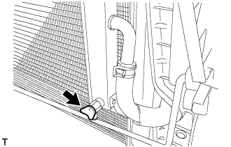
Close the bleeder plug.
Remove the plug and gasket shown in the illustration and drain the coolant.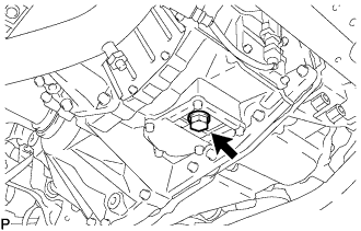
Install the plug with a new gasket.
- Torque:
- 39 N*m{ 398 kgf*cm , 29 ft.*lbf }
| 15. DRAIN ENGINE OIL |
Remove the oil filler cap.
Remove the oil drain plug, and drain the oil into a container.
Clean and install the oil drain plug with a new gasket.
- Torque:
- 45 N*m{ 459 kgf*cm , 33 ft.*lbf }
| 16. DRAIN HYBRID TRANSAXLE FLUID |
Using a socket hexagon wrench 10 mm, remove the filler plug and gasket.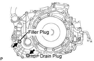
Using a socket hexagon wrench 10 mm, remove the drain plug and gasket.
Using a socket hexagon wrench 10 mm, install the drain plug, and a new gasket.
- Torque:
- 39 N*m{ 398 kgf*cm , 29 ft.*lbf }
| 17. REMOVE FRONT WIPER ARM AND BLADE ASSEMBLY RH |
Remove the 2 nuts and the front wiper arm and blade assembly RH.
| 18. REMOVE FRONT WIPER ARM AND BLADE ASSEMBLY LH |
Remove the nut and the front wiper arm and blade assembly LH.
| 19. REMOVE COWL TOP VENTILATOR LOUVER SUB-ASSEMBLY |
Remove the 2 clips.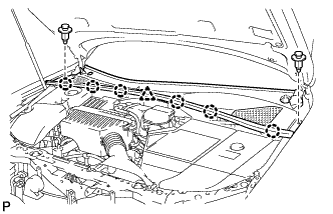
Disengage the 6 claws and the clamp, and remove the cowl top ventilator louver sub-assembly.
| 20. REMOVE WINDSHIELD WIPER MOTOR AND LINK ASSEMBLY |
Disconnect the connector.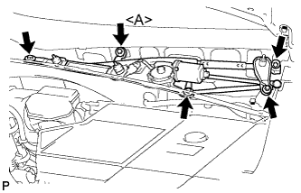
Remove the 5 bolts and the windshield wiper motor and link assembly.
- HINT:
- Bolt <A> cannot be removed because it is integrated into windshield wiper link assembly.
| 21. REMOVE COWL TOP PANEL SUB-ASSEMBLY OUTER |
Separate the wire harness clamp and grommet (A).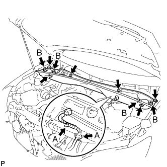
Remove the 4 shock absorber nuts (B).
Remove the 4 bolts, 2 nuts and cowl top panel sub-assembly.
Install the 4 shock absorber nuts.
- Torque:
- 80 N*m{ 815 kgf*cm , 59 ft.*lbf }
| 22. REMOVE BATTERY |
Remove the bolt and battery clamp.
Remove the battery and battery tray.
| 23. REMOVE BATTERY CARRIER SUB-ASSEMBLY |
Remove the 5 bolts and battery carrier.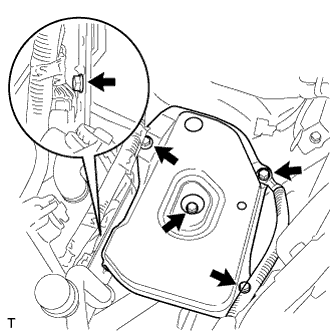
| 24. REMOVE COOL AIR INTAKE DUCT SEAL |
Remove the 4 clips and cool air intake duct seal.
| 25. REMOVE AIR CLEANER CAP W/ INLET |
Remove the 2 bolts, 4 clamps and air cleaner cap w/ inlet.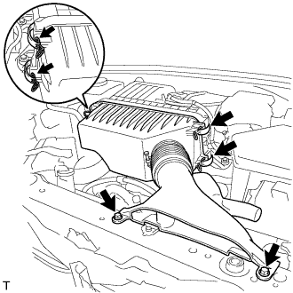
Remove the air cleaner filter element from the air cleaner case.
| 26. REMOVE AIR CLEANER CASE W/ RESONATOR |
Separate the ventilation hose No.2.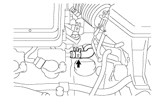
Disconnect the MAF meter connector.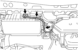
Disconnect the 2 wire harness clamps from the air cleaner.
Remove the 5 bolts from the air cleaner case w/ resonator.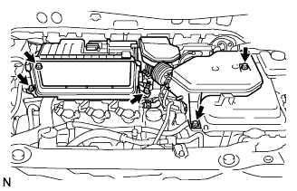
Remove the hose clamp, and separate the air cleaner hose No.1.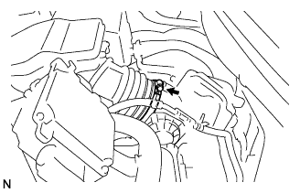
Remove the air cleaner case w/ resonator.
| 27. REMOVE INVERTER BRACKET NO.5 |
Remove the bolt and inverter bracket No.5.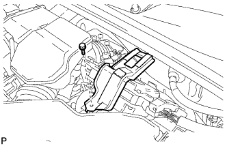
| 28. REMOVE POWER STEERING ECU ASSEMBLY |
Remove the bolt and ground cable terminal from the power steering ECU assembly.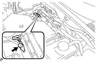
Release the locks of the 2 power steering ECU assembly connectors and disconnect the connectors.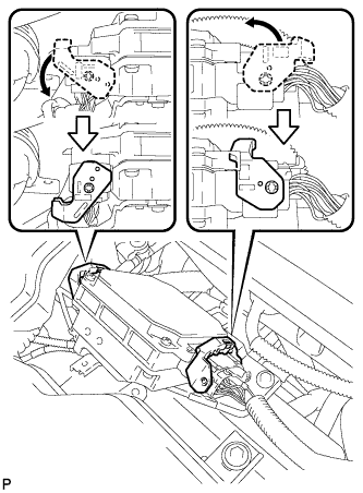
Separate the 2 wire harness clamps from the power steering ECU assembly.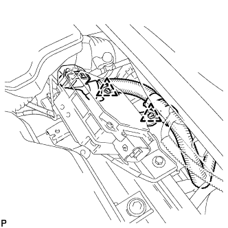
Remove the 2 bolts and the power steering ECU assembly.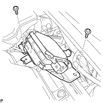
| 29. DISCONNECT CIRCUIT BREAKER SENSOR NO.1 |
Move the outer section to the wire harness side as illustrated, then disconnect the circuit breaker sensor No.1.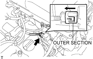
| 30. DISCONNECT ENGINE ROOM WIRE NO.2 |
Remove the nut from the engine room wire No.2.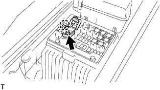
Release the claw, and disconnect the engine room wire No.2.
| 31. REMOVE INVERTER RESERVE TANK SUB-ASSEMBLY |
Remove the 2 bolts and inverter reserve tank sub-assembly.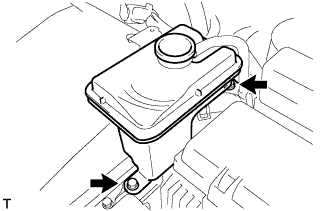
Slide the 2 clamps, and disconnect the 2 water hoses from the inverter reserve tank sub-assembly.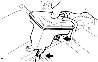
| 32. DISCONNECT WATER HOSE |
Slide the clamp, and disconnect the water hose from the w/ converter inverter assembly.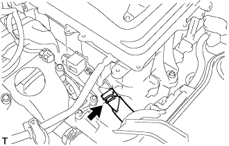
| 33. DISCONNECT POWER STEERING ECU BRACKET |
Remove the bolt, and disconnect the power steering ECU bracket.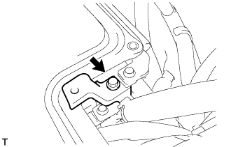
| 34. REMOVE INVERTER COVER |
Remove the bolt and interlock bracket.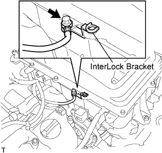
Insulate the removed terminal with insulating tape.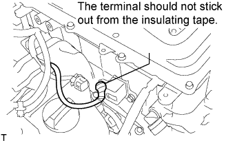
- NOTICE:
- Make sure that the terminal does not stick out from the insulating tape.
Remove the 12 bolts and inverter cover.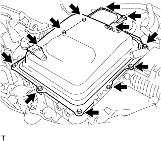
| 35. REMOVE VERIFY THAT VOLTAGE OF W/CONVERTER INVERTER ASSEMBLY IS 0V |
- CAUTION:
- Wear insulating gloves.
- NOTICE:
- Make sure that the inverter converter is temporarily installed before working on the converter inverter assembly. (Click here)
- Do not allow any foreign objects or waterdrops to enter the w/ converter inverter assembly.
- Make sure that the inverter converter is temporarily installed before working on the converter inverter assembly. (Click here)
Using the voltmeter, measure the voltage between the terminals of the 2 phase connectors (N-P).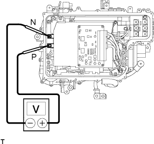
- Standard voltage:
- 0 V
- HINT:
- Use measuring range of DC 750 V or more on the voltmeter.
| 36. REMOVE ENGINE WIRE NO.4 |
- CAUTION:
- Wear insulating gloves.
- NOTICE:
- Make sure that the inverter converter is temporarily installed before working on the converter inverter assembly. (Click here)
- Do not allow any foreign objects or waterdrops to enter the w/ converter inverter assembly.
- Make sure that the inverter converter is temporarily installed before working on the converter inverter assembly. (Click here)
Remove the bolt, and disconnect the engine wire No.4 from the w/ converter inverter assembly.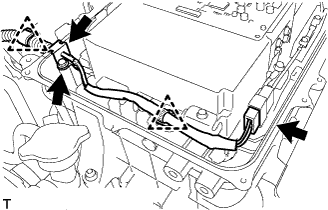
Disconnect the connector, clamps and grommet, and separate the engine wire No.4 from the w/ converter inverter assembly.
| 37. DISCONNECT HIGH VOLTAGE CABLE OF FRONT MOTOR |
- CAUTION:
- Wear insulating gloves.
- NOTICE:
- Make sure that the inverter converter is temporarily installed before working on the converter inverter assembly. (Click here)
- Insulate the removed terminals with insulating tape.
- Do not allow any foreign objects or waterdrops to enter the w/ converter inverter assembly.
- Make sure that the inverter converter is temporarily installed before working on the converter inverter assembly. (Click here)
Remove the 5 bolts, and disconnect the high voltage cables of the Motor from the w/ converter inverter assembly.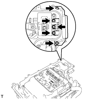
Remove the 5 bolts, and disconnect the high voltage cables of the Generator from the w/ converter inverter assembly.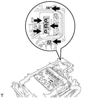
| 38. DISCONNECT MG ECU CONNECTOR |
- CAUTION:
- Wear insulating gloves.
- NOTICE:
- Make sure that the inverter converter is temporarily installed before working on the converter inverter assembly. (Click here)
- Do not allow any foreign objects or waterdrops to enter the w/ converter inverter assembly.
- Make sure that the inverter converter is temporarily installed before working on the converter inverter assembly. (Click here)
Disconnect the 2 connectors and grommets from the w/ converter inverter assembly.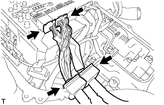
| 39. DISCONNECT NO.3 WIRE FRAME |
- CAUTION:
- Wear insulating gloves.
- NOTICE:
- Make sure that the inverter converter is temporarily installed before working on the converter inverter assembly. (Click here)
- Insulate the removed terminals with insulating tape.
- Do not allow any foreign objects or waterdrops to enter the w/ converter inverter assembly.
- Make sure that the inverter converter is temporarily installed before working on the converter inverter assembly. (Click here)
Remove the 5 bolts, and disconnect the No.3 wire frame (high voltage cables of the rear motor) from the w/ converter inverter assembly.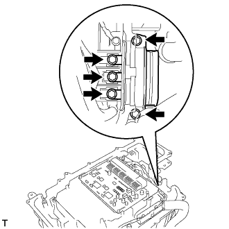
Remove the bolt and lift the lever to disconnect the No.3 wire frame from the w/ converter inverter assembly.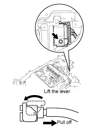
| 40. INSTALL INVERTER COVER |
Temporarily install the inverter cover with the 2 bolts to prevent any foreign objects or waterdrops from entering the w/ converter inverter assembly.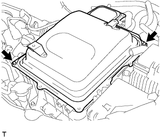
| 41. SEPARATE ENGINE ROOM RELAY BLOCK ASSEMBLY |
Disconnect the clamp, and release the engine room relay block assembly.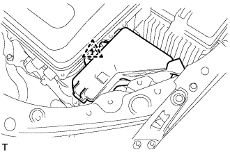
| 42. REMOVE INVERTER BRACKET NO.4 |
Remove the 2 bolts and inverter bracket No.4.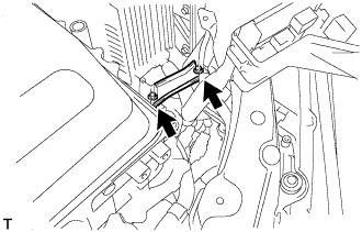
| 43. REMOVE W/ CONVERTER INVERTER ASSEMBLY |
- CAUTION:
- Wear insulating gloves.
Remove the 2 nuts, bolt and w/ converter inverter assembly.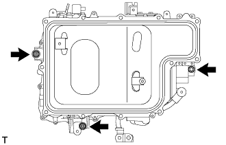
- NOTICE:
- 2 people are needed to remove the w/ converter inverter assembly.
- If removing and storing the w/ converter inverter assembly, make sure to install the inverter cover to prevent any foreign objects or warterdrops from entering the w/ converter inverter assembly.
- Attach tape or equivalent (any adhesive should not be remained) to the holes for the connectors and grommets to prevent foreign matter or water from entering.
- 2 people are needed to remove the w/ converter inverter assembly.
| 44. REMOVE BRAKE MASTER CYLINDER RESERVOIR SUB-ASSEMBLY |
Disconnect the connector.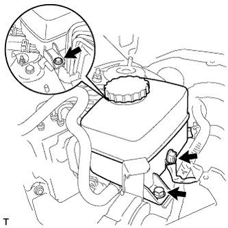
Remove the 2 bolts and separate the brake master cylinder reservoir.
| 45. REMOVE RESERVOIR BRACKET |
Disconnect the clamp.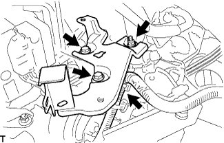
Remove the nut, 2 bolts and reservoir bracket.
| 46. REMOVE AIR CLEANER BRACKET |
Remove the 2 bolts and air cleaner bracket.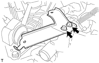
| 47. REMOVE ENGINE MOVING CONTROL ROD |
Remove the 4 bolts, the engine moving control rod and the bracket.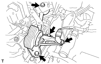
| 48. REMOVE ENGINE MOUNTING STAY NO.2 RH |
Remove the bolt, the engine mounting stay No.2 and the engine mounting bracket No.2.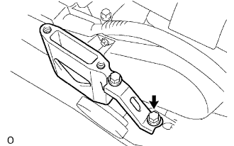
| 49. SEPARATE COMPRESSOR W/ MOTOR ASSEMBLY |
Disconnect the 2 connectors.
Remove the 3 bolts and compressor w/ motor assembly.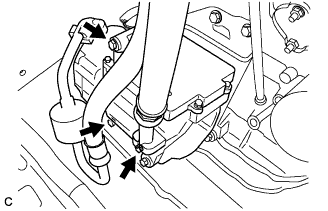
- HINT:
- Disconnect the compressor assembly together with the low-pressure and high-pressure hoses, then secure it to the vehicle side with rope.
| 50. REMOVE INVERTER BRACKET NO.1 |
Separate the 3 hose clamps.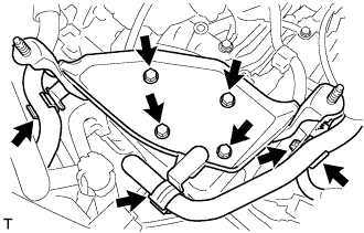
Remove the 4 bolts, harness clamp and inverter bracket.
| 51. SEPARATE TRANSMISSION CONTROL CABLE ASSEMBLY |
Remove the nut and separate the control shaft lever from the position sensor.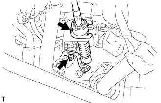
Remove the clip and disconnect the control cable from the bracket.
Remove the bolt and separate the control cable from the transaxle.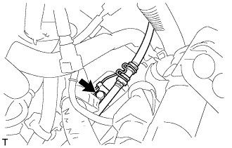
| 52. DISCONNECT FUEL VAPOR FEED HOSE |
| 53. DISCONNECT FUEL PIPE SUB-ASSEMBLY NO.1 |
Remove the EFI fuel pipe clamp.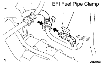
Pinch the retainer as illustrated, then pull out the fuel tube connector from the pipe.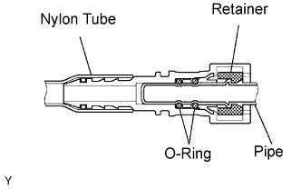
- NOTICE:
- Remove any dirt and foreign objects on the fuel tube connector before performing this work.
- Do not allow any scratches or foreign objects on the parts when disconnecting, as the fuel tube connector has the O-rings that seal the pipe.
- Perform this work by hand. Do not use any tools.
- Do not forcibly bend, twist or turn the nylon tube.
- Protect the disconnected part by covering it with a vinyl bag after disconnecting the fuel tube.
- If the fuel tube connector and pipe are stuck, push and pull them to release.
- Remove any dirt and foreign objects on the fuel tube connector before performing this work.
| 54. DISCONNECT HEATER WATER INLET HOSE |
Using pliers, grip the claws of the clip and slide the clip to disconnect the heater water inlet hose.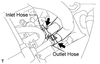
| 55. DISCONNECT HEATER WATER OUTLET HOSE |
- HINT:
- Disconnection of the heater water outlet hose is the same as for the heater water inlet hose.
| 56. DISCONNECT RADIATOR HOSE INLET |
| 57. DISCONNECT RADIATOR HOSE OUTLET |
| 58. DISCONNECT OIL COOLER INLET TUBE SUB-ASSEMBLY |
Using pliers, grip the claws of the clip and slide the clip to disconnect the oil cooler inlet tube.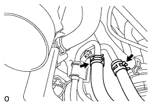
| 59. DISCONNECT OIL COOLER OUTLET TUBE SUB-ASSEMBLY |
- HINT:
- Disconnection of the oil cooler outlet tube is the same as for the oil cooler inlet tube.
| 60. REMOVE HEATER WATER PUMP ASSEMBLY |
Disconnect the connector.
Remove the bolt and heater water pump.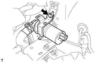
| 61. DISCONNECT WATER HOSE |
| 62. REMOVE INSTRUMENT PANEL NO.2 UNDER COVER SUB-ASSEMBLY |
Using a screwdriver, push the 3 claws in the direction indicated by the arrow to disengage and remove the guide on the front of the vehicle.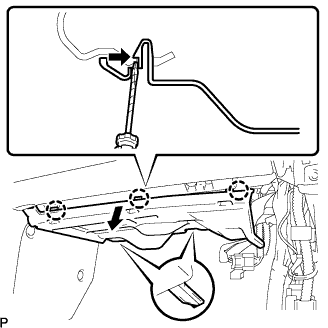
- HINT:
- Tape the screwdriver tip before use.
Disconnect the connectors and remove the instrument panel No.2 under cover sub-assembly.
| 63. REMOVE GLOVE COMPARTMENT DOOR ASSEMBLY |
Remove the 2 bolts <A> and the 2 screws <C>.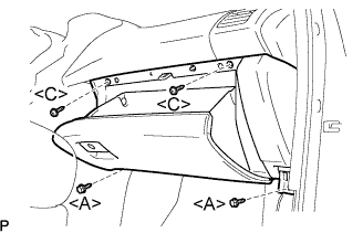
Pull the glove compartment door assembly to the rear to remove it.
Disconnect the connector.
| 64. SEPARATE ENGINE WIRE |
Disconnect the engine wire harness from the ECM and the junction block.
Remove the 2 nuts and pull out the engine wire harness.
Remove the body ground and connector.
| 65. DISCONNECT WIRE HARNESS |
Disconnect the power steering link connector and clamp.
Remove the ground cable.
| 66. REMOVE EXHAUST PIPE ASSEMBLY FRONT |
Disconnect the heated oxygen sensor connector.
Remove the 2 bolts, 2 nuts and exhaust pipe assembly front.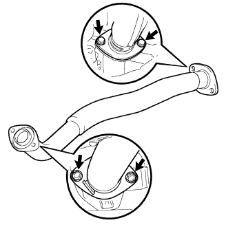
Remove the 2 gaskets.
| 67. REMOVE EXHAUST PIPE SUB-ASSEMBLY FRONT NO.3 |
Disconnect the heated oxygen sensor connector.
Remove the 2 bolts, 2 nuts and exhaust pipe sub-assembly front No.3.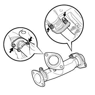
Remove the 2 gaskets.
| 68. SEPARATE FRONT STABILIZER LINK ASSEMBLY LH |
Support the front suspension lower arm No.1 with a jack using a wooden block to avoid damage.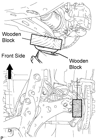
Remove the nut and separate the front stabilizer link assembly from the front shock absorber.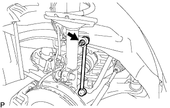
- HINT:
- If the ball joint turns together with the nut, use a hexagon wrench (6 mm) to hold the stud.
| 69. SEPARATE FRONT STABILIZER LINK ASSEMBLY RH |
- HINT:
- Perform the same procedure as above on the opposite side.
| 70. REMOVE FRONT AXLE HUB LH NUT |
Using SST and a hammer, release the staked part of the front axle hub nut.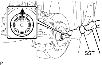
- SST
- 09930-00010
Using a socket wrench (30 mm), remove the axle hub nut.
- NOTICE:
- Loosen the staked part of the nut completely, otherwise the screw of the drive shaft may be damaged.
| 71. REMOVE FRONT AXLE HUB RH NUT |
- HINT:
- Perform the same procedure as above on the opposite side.
| 72. SEPARATE SPEED SENSOR FRONT LH |
Remove the 2 bolts and clip, and separate the sensor wire and hose from the shock absorber.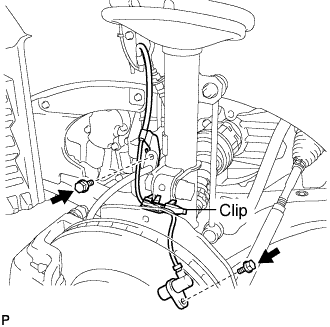
- NOTICE:
- Be careful not to damage the speed sensor.
| 73. SEPARATE SPEED SENSOR FRONT RH |
- HINT:
- Perform the same procedure as above on the opposite side.
| 74. SEPARATE TIE ROD END SUB-ASSEMBLY LH |
Remove the cotter pin and the nut.
Using SST, separate the tie rod assembly LH from the steering knuckle.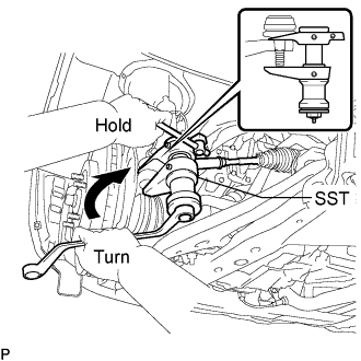
- SST
- 09628-00011
- NOTICE:
- Hang SST with a string, etc. to prevent it from falling.
- Do not damage the front disc brake dust cover.
- Do not damage the ball joint dust cover.
- Do not damage the steering knuckle.
- Hang SST with a string, etc. to prevent it from falling.
| 75. SEPARATE TIE ROD END SUB-ASSEMBLY RH |
- HINT:
- Perform the same procedure as above on the opposite side.
| 76. SEPARATE FRONT SUSPENSION ARM SUB-ASSEMBLY LOWER NO.1 LH |
Remove the bolt and 2 nuts, and separate the front suspension arm sub-assembly lower No.1 from the lower ball joint.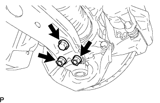
| 77. SEPARATE FRONT SUSPENSION ARM SUB-ASSEMBLY LOWER NO.1 RH |
- HINT:
- Perform the same procedure as above on the opposite side.
| 78. SEPARATE FRONT AXLE ASSEMBLY LH |
Using a plastic hammer, separate the drive shaft from the axle hub.
- NOTICE:
- Be careful not to damage the boot and speed sensor rotor.
| 79. SEPARATE FRONT AXLE ASSEMBLY RH |
- HINT:
- Perform the same procedure as above on the opposite side.
| 80. SEPARATE STEERING INTERMEDIATE SHAFT SUB-ASSEMBLY |
Fix the steering wheel with the seat belt in order to prevent rotation.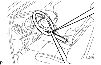
- HINT:
- This operation is useful to prevent damage to the spiral cable.
Loosen the bolt (A) and remove the clamp from the steering column hole shield.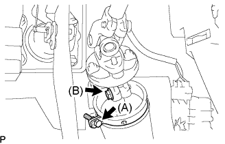
Loosen the bolt (B).
- HINT:
- Do not remove the bolt (B).
Remove the bolt, and then slide the steering intermediate shaft sub-assembly.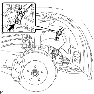
- NOTICE:
- Do not separate the steering intermediate shaft sub-assembly.
Put matchmarks on the steering intermediate shaft sub-assembly and the power steering link assembly.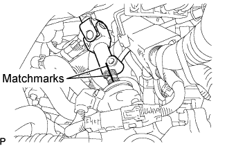
Separate the steering intermediate shaft sub-assembly from the power steering link assembly.
| 81. REMOVE ENGINE ASSEMBLY WITH TRANSAXLE |
Set the engine lifter.
Remove the 6 bolts and 2 nuts, then remove the frame side rail plates RH and LH.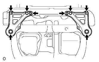
Remove the 6 bolts and 2 nuts, then remove the front suspension member brace rear RH and LH.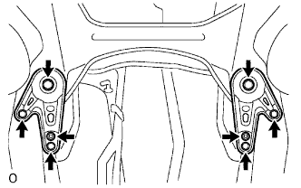
Carefully remove the engine assembly from the vehicle.
Install the No.2 engine hanger in the correct direction shown in the illustration.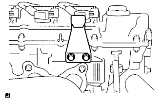
- Torque:
- 20 N*m{ 200 kgf*cm , 14 ft.*lbf }
- HINT:
- Part No.
No.2 engine hanger
12282-20020
Bolt
91621-60822
Attach the engine sling and hang the engine assembly with the chain block.
| 82. REMOVE ENGINE WIRE |
| 83. REMOVE EXHAUST MANIFOLD HEAT INSULATOR NO.1 |
Remove the 3 bolts and exhaust manifold heat insulator No.1.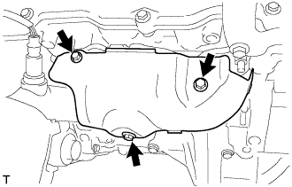
| 84. REMOVE MANIFOLD STAY |
Remove the 2 bolts and manifold stay.
| 85. REMOVE EXHAUST MANIFOLD SUB-ASSEMBLY RH |
Disconnect the heated oxygen sensor connector.
Using several steps, loosen and remove the 6 nuts in the sequence shown in the illustration.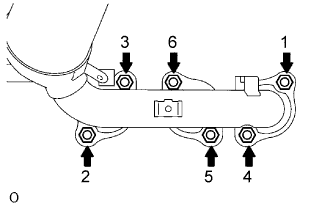
Remove the exhaust manifold RH and the gasket from the cylinder head RH.
| 86. REMOVE HV TRANSAXLE MASS DAMPER |
Remove the bolt and transaxle mass damper.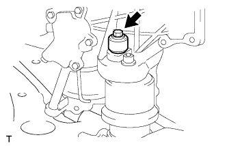
| 87. REMOVE FRONT FRAME ASSEMBLY |
Remove the 2 nuts and separate the engine mounting insulators RH and LH.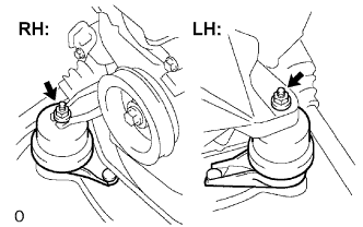
Remove the nut and separate engine mounting insulator FR.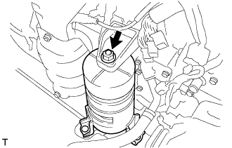
Remove the 2 bolts and separate the engine mounting insulator RR.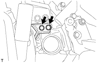
| 88. REMOVE FRONT DRIVE SHAFT ASSEMBLY LH |
Using SST, remove the front drive shaft assembly LH.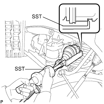
- SST
- 09520-01010
09520-24010 (09520-32040)
- NOTICE:
- Be careful not to damage the transaxle case oil seal and inboard joint boot.
- Be careful not to drop the drive shaft assembly.
- Be careful not to damage the transaxle case oil seal and inboard joint boot.
| 89. REMOVE FRONT DRIVE SHAFT ASSEMBLY RH |
Using pliers, remove the bearing bracket hole snap ring.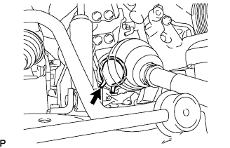
Remove the bolt from the drive shaft bearing bracket.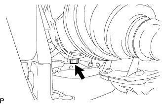
Using SST, remove the front drive shaft assembly RH.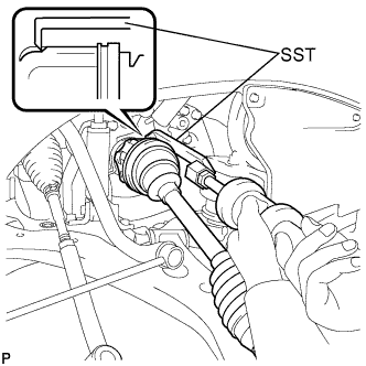
- SST
- 09520-01010
09520-24010 (09520-32040)
- NOTICE:
- Be careful not to damage the transaxle case oil seal and inboard joint boot.
- Be careful not to drop the drive shaft assembly.
- Be careful not to damage the transaxle case oil seal and inboard joint boot.
| 90. REMOVE FLYWHEEL HOUSING UNDER COVER |
Remove the 2 bolts and flywheel housing under cover.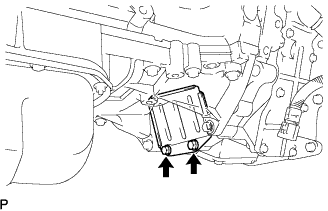
| 91. REMOVE ENGINE MOUNTING BRACKET FRONT |
Remove the 3 bolts and engine mounting bracket.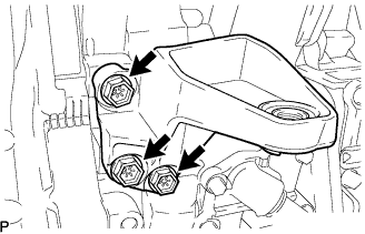
| 92. REMOVE HYBRID VEHICLE TRANSAXLE ASSEMBLY |
Remove the 8 bolts.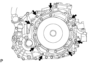
Separate and remove the hybrid vehicle transaxle.
- NOTICE:
- Do not pry out the connection between the transaxle assembly and engine more than necessary to prevent the knock pin from being damaged.
| 93. REMOVE TRANSMISSION INPUT DAMPER ASSEMBLY |
Using SST, hold the crankshaft.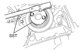
- SST
- 09213-54015
(91651-60855)
09330-00021
Remove the 6 bolts and transmission input damper from the flywheel.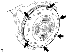
| 94. REMOVE FLYWHEEL SUB-ASSEMBLY |
Using SST, hold the crankshaft.
- SST
- 09213-54015
(91651-60855)
09330-00021
Remove the 8 bolts and flywheel.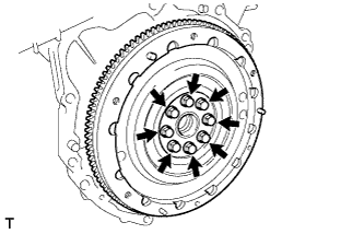
| 95. INSTALL ENGINE STAND |
| 96. REMOVE ENGINE HANGER NO.2 |
Remove the 2 bolts and engine hanger No.2.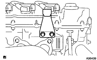
| 97. REMOVE EMISSION CONTROL VALVE SET |
Disconnect the VSV connector (A).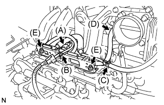
Remove the wire harness clamp (B).
Disconnect the fuel vapor feed hose No. 1 (C).
Disconnect the fuel vapor feed hose No. 2 (D).
Remove the 2 nuts (E), then remove the emission control valve set.
| 98. REMOVE INTAKE AIR SURGE TANK |
Disconnect the throttle motor connector (A).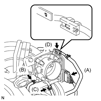
Separate the water by-pass hose No. 2 (B).
Separate the water by-pass hose No. 3 (C).
Separate the fuel vapor feed hose (D).
Disconnect the ventilation hose.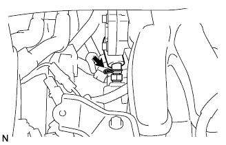
Remove the 2 bolts, then remove the engine hanger No.1 (A).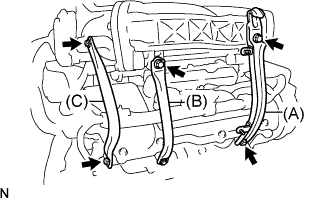
Remove the 2 bolts, then remove the surge tank stay No. 1 (B).
Remove the 2 bolts, then remove the surge tank stay No. 2 (C).
Disconnect the ground cable connector.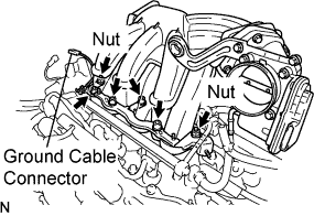
Using a socket hexagon wrench 8 mm, remove the 4 bolts.
Remove the 2 nuts, then remove the emission control valve bracket and the intake air surge tank.
Remove the gasket from the intake air surge tank.
| 99. REMOVE INTAKE MANIFOLD |
Remove the nut and disconnect the ground cable (A).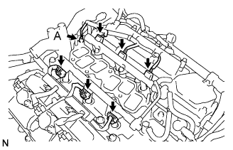
Disconnect the 6 fuel injector connectors.
In order to remove the intake manifold, using several steps, remove the 9 bolts and 2 nuts in the sequence shown in the illustration.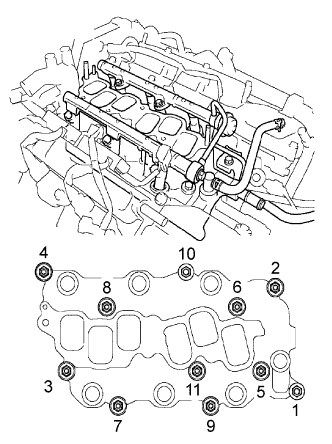
| 100. REMOVE WATER OUTLET |
Disconnect the ground cable connector (A).
Disconnect the engine coolant temperature sensor connector (B).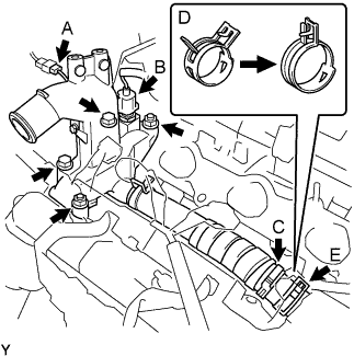
Remove the clamp (C).
Remove the 2 bolts, 2 nuts and 2 washers.
Lock the hose clamp as shown in the illustration (D) and remove the water outlet together with water by-pass hose No.1 (E).
Remove the 2 gaskets from the 2 cylinder heads.
| 101. REMOVE IGNITION COIL ASSEMBLY |
| 102. REMOVE MANIFOLD CONVERTER INSULATOR NO.3 |
Remove the bolt, nut and manifold converter insulator No.3.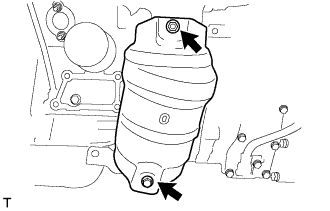
| 103. REMOVE EXHAUST MANIFOLD HEAT INSULATOR NO.2 |
Remove the 2 bolts and manifold heat insulator No.2.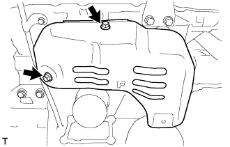
| 104. REMOVE EXHAUST MANIFOLD CONVERTER SUB-ASSEMBLY NO.2 |
Disconnect the heated oxygen sensor connector.
Using several steps, loosen and remove the 6 nuts and bolt in the sequence shown in the illustration.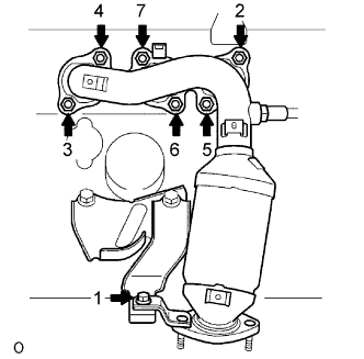
Remove the exhaust manifold converter No.2 and the gasket from the cylinder head LH.
| 105. REMOVE MANIFOLD STAY NO.2 |
Remove the 2 bolts and manifold stay No.2.
| 106. REMOVE ENGINE MOUNTING BRACKET REAR |
Remove the 3 bolts and engine mounting bracket rear.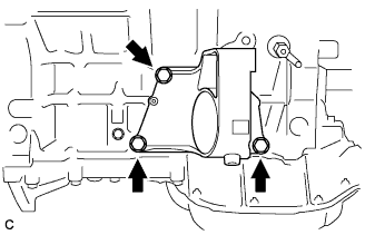
| 107. REMOVE ENGINE MOUNTING BRACKET RH |
Remove the 3 bolts and engine mounting bracket RH.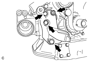
| 108. REMOVE ENGINE MOUNTING STAY BRACKET |
Remove the bolt, nut and engine mounting stay bracket.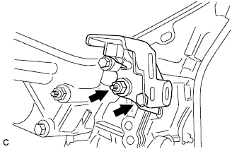
| 109. REMOVE COMPRESSOR MOUNTING BRACKET NO.1 |
Remove the 4 bolts and compressor mounting bracket.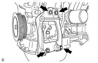
| 110. REMOVE INTAKE AIR CONNECTOR BRACKET NO.2 |
Remove the 2 bolts and intake air connector bracket No.2.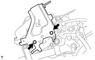
| 111. REMOVE WATER INLET PIPE |
Remove the bolt and the water inlet pipe.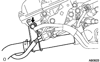
Remove the O-ring from the water inlet pipe.
| 112. REMOVE WATER INLET |
Disconnect the wire harness clamp.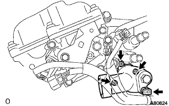
Remove the 3 nuts and the water inlet.
| 113. REMOVE THERMOSTAT |
| 114. REMOVE ENGINE OIL PRESSURE SWITCH ASSEMBLY |
Using a deep socket wrench 24 mm, remove the oil pressure switch.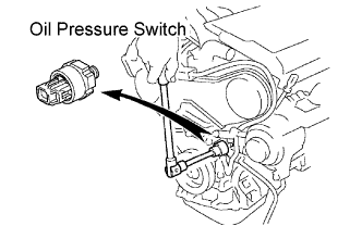
| 115. REMOVE KNOCK CONTROL SENSOR |
Disconnect the 2 knock sensor connectors.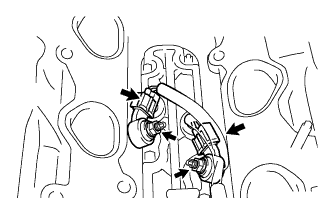
Remove the 2 nuts, and then remove the 2 knock sensors.
| 116. REPLACE PARTIAL ENGINE ASSEMBLY |