Driver Side Double Lock Motor Circuit
Circuit diagnosis
DESCRIPTION
The driver's door double lock motor is built into the driver's door lock assembly.The door opening relay receives driver's door double door lock set/release signals from the body ECU using multiplex communication.
The door opening relay controls the double lock motor to set/release the double door lock. This relay applies current from terminal ACTS to terminal ACTR to operate the motor to set the lock. It reverses the direction of the current to operate the motor to release the lock.
WIRING DIAGRAM
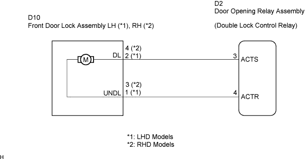

INSPECTION PROCEDURE
| 1. INSPECT FRONT DOOR LOCK ASSEMBLY LH,RH (DOUBLE LOCK MOTOR) |

LHD Models:Remove the front door lock assembly LH.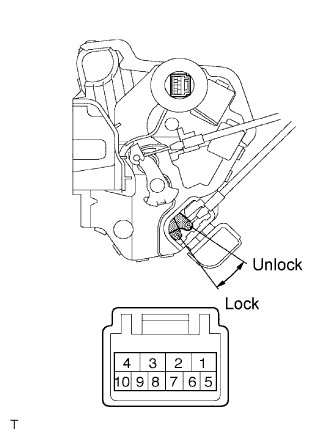
Apply battery voltage and set the door lock motor to the lock position.
- OK:
Measurement Condition
Specified Condition
Battery positive (+) →Terminal 4
Battery negative (-) →Terminal 3
Lock
Apply battery voltage to the door lock and check operation of the double lock motor.
- OK:
Measurement Condition
Specified Condition
Battery positive (+) →Terminal 2
Battery negative (-) →Terminal 1
Double Locking System is set
Battery positive (+) →Terminal 1
Battery negative (-) →Terminal 2
Double Locking System is unset
Check that the doors cannot be unlocked by operating the control cable while the double locking system is set.
RHD Models:Remove the front door lock assembly RH.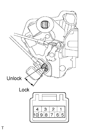
Apply battery voltage and set the door lock motor to the lock position.
- OK:
Measurement Condition
Specified Condition
Battery positive (+) →Terminal 2
Battery negative (-) →Terminal 1
Lock
Apply battery voltage to the door lock and check operation of the double lock motor.
- OK:
Measurement Condition
Specified Condition
Battery positive (+) →Terminal 4
Battery negative (-) →Terminal 3
Double Locking System is set
Battery positive (+) →Terminal 3
Battery negative (-) →Terminal 4
Double Locking System is unset
Check that the doors cannot be unlocked by operating the control cable while the double locking system is set.
|
|
||||

| OK | |
 |
| 2. CHECK WIRE HARNESS (FRONT DOOR LOCK ASSEMBLY LH,RH - DOOR OPENING RELAY ASSEMBLY) |
LHD Models:Disconnect the Front Door Lock Assembly LH connector.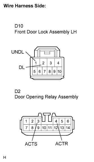
Disconnect the door opening relay assembly connector.
Measure the resistance according to the value(s) in the table below.
- Standard resistance:
Tester Connection
Condition
Specified Condition
D10-2 (DL) - D2-3 (ACTS)
Always
Below 1 Ω
D10-1 (UNDL) - D2-4 (ACTR)
Always
Below 1 Ω
RHD Models:Disconnect the Front Door Lock Assembly RH connector.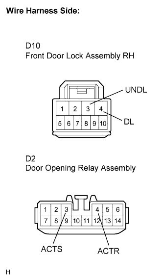
Disconnect the door opening relay assembly connector.
Measure the resistance according to the value(s) in the table below.
- Standard resistance:
Tester Connection
Condition
Specified Condition
D10-4 (DL) - D2-3 (ACTS)
Always
Below 1 Ω
D10-3 (UNDL) - D2-4 (ACTR)
Always
Below 1 Ω
|
|
||||
| OK | ||
 |
||
| ||