Fuel Receiver Gauge Malfunction
Circuit diagnosis
WIRING DIAGRAM
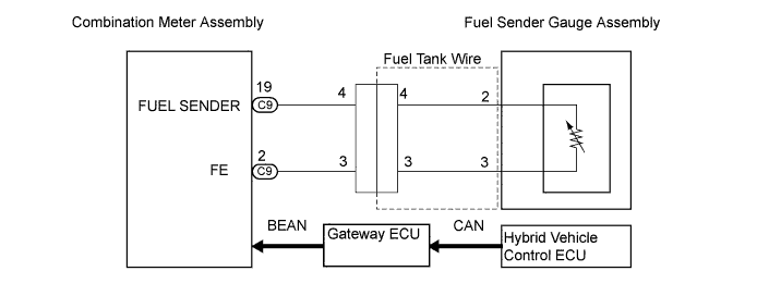

INSPECTION PROCEDURE
| 1. PERFORM ACTIVE TEST BY INTELLIGENT TESTER |

Operate the intelligent tester according to the steps on the display and select "ACTIVE TEST".
METER Item
Test Details
Diagnostic Note
Fuel Meter Operation
OFF, EMPTY, 1/2, FULL
-
- OK:
- Needle indication is normal.
|
|
||||

| OK | |
 |
| 2. READ VALUE OF INTELLIGENT TESTER |
Operate the intelligent tester according to the steps on the display and select "DATA LIST".
METER Item
Measurement Item/Range (Display)
Normal Condition
Diagnostic Note
Fuel Input
Fuel input signal Min.: 0, Max.: 255
Fuel gauge indicates (F): 47
Fuel gauge indicates (1/2): 148
Fuel gauge indicates (E): 205
-
- OK:
- Fuel value signal displayed on the tester is almost the same as needle indication.
|
|
||||
| NG | |
|
| 3. INSPECT COMBINATION METER ASSEMBLY |
Disconnect the fuel tank wire.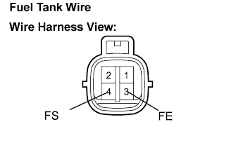
Shorten the terminals 3 (FE) and 4 (FS) on wire harness side.
Disconnect the battery (-) terminal, then reconnect.
Turn the ignition switch to the ON position.
- OK:
- Fuel receiver gauge indicates F or more.
|
|
||||

| NG | |
|
| 4. CHECK HARNESS AND CONNECTOR (BETWEEN COMBINATION METER AND FUEL TANK WIRE) |
Disconnect the C9 connector and fuel tank wire.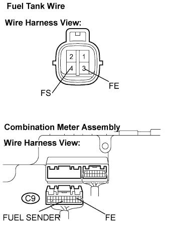
Measure the resistance according to the value(s) in the table below.
- Standard Resistance:
Tester Connection
Condition
Specified Condition
C9-2 (FE) -
C9-19 (FUEL SENDER)
Always
Below 1 Ω
C9-19 (FUEL SENDER)
- Body ground
Always
10 kΩ or higher
|
|
||||
| OK | |
|
| 5. REPLACE COMBINATION METER ASSEMBLY |
| NG | ||
 |
||
| ||
| 6. INSPECT FUEL TANK WIRE |
Disconnect the fuel tank wire from the fuel sender gauge assembly.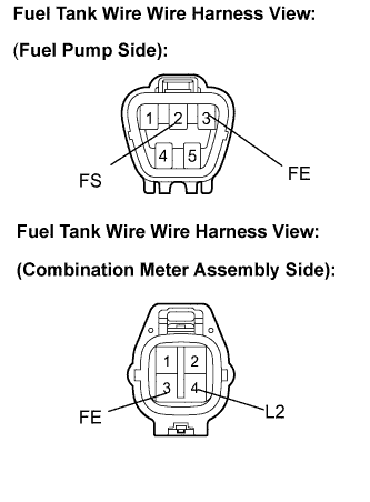
Measure the resistance according to the value(s) in the table below.
- Standard Resistance:
Tester Connection
Condition
Specified Condition
2 (FS) - 4 (L2)
Always
Below 1 Ω
3 (FE) - 3 (FE)
Always
Below 1 Ω
4 (L2) - Body ground
Always
10 kΩ or higher
|
|
||||
| OK | |
|
| 7. INSPECT FUEL SENDER GAUGE ASSEMBLY |
Check the operation of the float moving smoothly between F and E.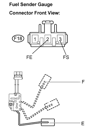
Disconnect the fuel sender gauge connector.
Remove the fuel sender gauge assembly.
Measure the resistance between the terminals 2 (FE) and 3 (FS) of connector according to the value(s) in the table below.
- Standard Resistance:
Float Level
Resistance (Ω)
F
13.5 to 16.5
E
405.5 to 414.5
|
|
||||
| OK | ||
|
||
| ||