Speedometer Malfunction
Circuit diagnosis
WIRING DIAGRAM
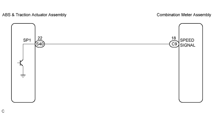

INSPECTION PROCEDURE
| 1. PERFORM ACTIVE TEST BY INTELLIGENT TESTER |

Operate the intelligent tester according to the steps on the display and select "ACTIVE TEST".
METER Item
Test Details
Diagnostic Note
Speed Meter Operation
0 / 40 (24) / 80 (48) / 120 (72) / 160 (96) / 200 (120) km/h (mph)
-
- OK:
- Needle indication is within the allowable range.
|
|
||||

| OK | |
 |
| 2. READ VALUE OF INTELLIGENT TESTER |
Operate the intelligent tester according to the steps on the display and select "DATA LIST".
METER Item
Measurement Item/Range (Display)
Normal Condition
Diagnostic Note
Vehicle Speed Meter
Vehicle speed / Min.: 0 km/h (0 mph), Max.: 255 km/h (158 mph)
Almost same as actual speed (When driving)
-
- OK:
- Vehicle speed displayed on the tester is almost the same as the actual vehicle speed.
|
|
||||

| OK | ||
 |
||
| ||
| 3. READ VALUE OF INTELLIGENT TESTER |
Operate the intelligent tester according to the steps on the display and select "DATA LIST".
ABS Item
Measurement Item/Range (Display)
Normal Condition
Diagnostic Note
FR/FL/RR/RL Wheel Speed
Vehicle speed / Min.: 0 km/h (0 mph), Max.: 326 km/h (202 mph)
Almost same as actual speed (When driving)
-
- OK:
- Vehicle speed displayed on the tester is almost the same as the actual vehicle speed.
|
|
||||
| OK | |
|
| 4. INSPECT COMBINATION METER ASSEMBLY |
Disconnect the S40 connector.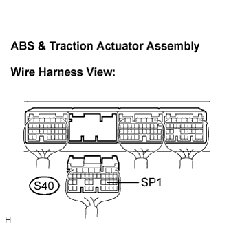
Measure the voltage according to the value(s) in the table below.
- Standard Voltage:
Tester Connection
Condition
Specified Condition
S40-22 (SP1) - Body ground
Turn the ignition switch to the ON position.
10 to 14 V
|
|
||||
| OK | |
|
| 5. INSPECT COMBINATION METER ASSEMBLY |
Check the input signal waveform.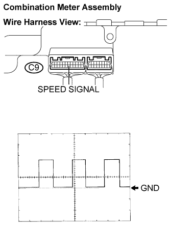
Remove the combination meter assembly with connector(s) still connected.
Connect the oscilloscope to the terminals C9-18 (SPEED SIGNAL) and body ground.
Start the engine.
Check the signal waveform according to the condition(s) in the table below.
OK Item
Condition
Tool setting
5 V/DIV., 20 ms/DIV.
Vehicle condition
Driving at approx. 20 km/h (12 mph)
- OK:
- The waveform is displayed as shown in the illustration.
- HINT:
- As the vehicle speed increases, the cycle of the signal waveform narrows.
|
|
||||
| OK | ||
|
||
| ||
| 6. CHECK HARNESS AND CONNECTOR (COMBINATION METER AND ABS & TRACTION ACTUATOR ASSEMBLY) |
Disconnect the C9 and S40 connectors.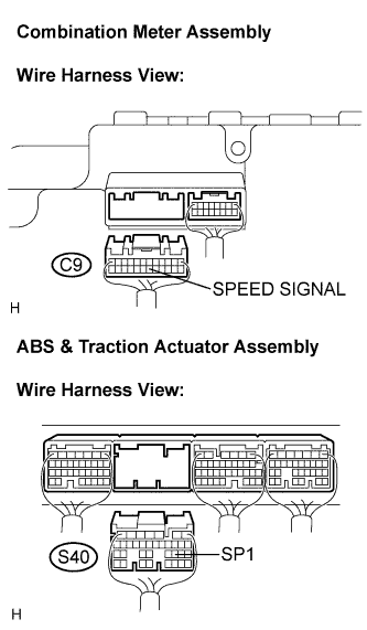
Measure the resistance according to the value(s) in the table below.
- Standard Resistance:
Tester Connection
Condition
Specified Condition
C9-18 (SPEED SIGNAL)
S40-22 (SP1)
Always
Below 1 Ω
C9-18 (SPEED SIGNAL)
- Body ground
Always
10 kΩ or higher
|
|
||||
| OK | ||
|
||
| ||