REMOVAL
Removal / installation
| 1. REMOVE ENGINE ASSEMBLY WITH TRANSAXLE |

| 2. REMOVE ENGINE WIRE |
| 3. REMOVE EXHAUST MANIFOLD HEAT INSULATOR NO.1 |
Remove the 3 bolts and exhaust manifold heat insulator No.1.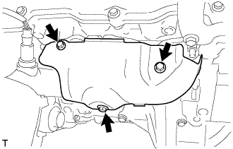

| 4. REMOVE MANIFOLD STAY |
Remove the 2 bolts and manifold stay.
| 5. REMOVE EXHAUST MANIFOLD SUB-ASSEMBLY RH |
Disconnect the heated oxygen sensor connector.
Using several steps, loosen and remove the 6 nuts in the sequence shown in the illustration.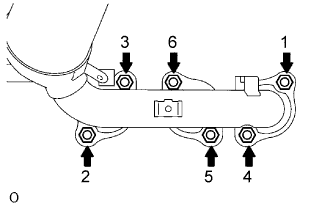
Remove the exhaust manifold RH and the gasket from the cylinder head RH.
| 6. REMOVE HV TRANSAXLE MASS DAMPER |
Remove the bolt and transaxle mass damper.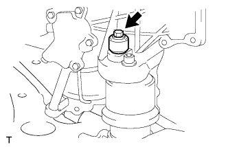
| 7. REMOVE FRONT FRAME ASSEMBLY |
Remove the 2 nuts and separate the engine mounting insulators RH and LH.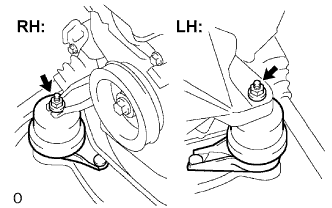
Remove the nut and separate engine mounting insulator FR.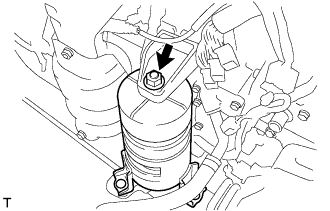
Remove the 2 bolts and separate the engine mounting insulator RR.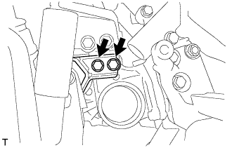
| 8. REMOVE FRONT DRIVE SHAFT ASSEMBLY LH |
Using SST, remove the front drive shaft assembly LH.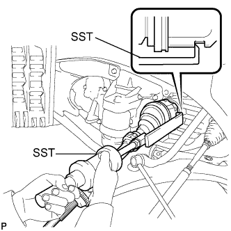
- SST
- 09520-01010
09520-24010 (09520-32040)
- NOTICE:
- Be careful not to damage the transaxle case oil seal and inboard joint boot.
- Be careful not to drop the drive shaft assembly.
- Be careful not to damage the transaxle case oil seal and inboard joint boot.
| 9. REMOVE FRONT DRIVE SHAFT ASSEMBLY RH |
Using pliers, remove the bearing bracket hole snap ring.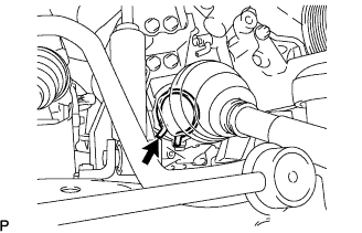
Remove the bolt from the drive shaft bearing bracket.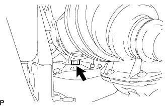
Using SST, remove the front drive shaft assembly RH.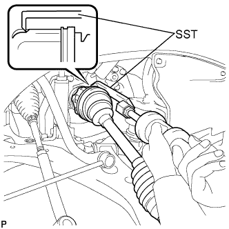
- SST
- 09520-01010
09520-24010 (09520-32040)
- NOTICE:
- Be careful not to damage the transaxle case oil seal and inboard joint boot.
- Be careful not to drop the drive shaft assembly.
- Be careful not to damage the transaxle case oil seal and inboard joint boot.
| 10. REMOVE FLYWHEEL HOUSING UNDER COVER |
Remove the 2 bolts and flywheel housing under cover.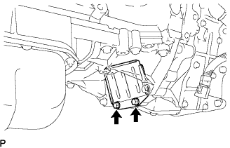
| 11. REMOVE ENGINE MOUNTING BRACKET FRONT |
Remove the 3 bolts and engine mounting bracket.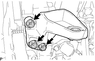
| 12. REMOVE HYBRID VEHICLE TRANSAXLE ASSEMBLY |
Remove the 8 bolts.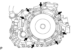
Separate and remove the hybrid vehicle transaxle.
- NOTICE:
- Do not pry out the connection between the transaxle assembly and engine more than necessary to prevent the knock pin from being damaged.
| 13. REMOVE TRANSMISSION INPUT DAMPER ASSEMBLY |
Using SST, hold the crankshaft.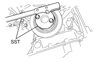
- SST
- 09213-54015
(91651-60855)
09330-00021
Remove the 6 bolts and transmission input damper from the flywheel.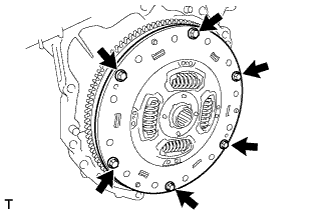
| 14. REMOVE FLYWHEEL SUB-ASSEMBLY |
Using SST, hold the crankshaft.
- SST
- 09213-54015
(91651-60855)
09330-00021
Remove the 8 bolts and flywheel.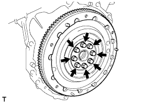
| 15. INSTALL ENGINE STAND |
| 16. REMOVE MANIFOLD CONVERTER INSULATOR NO.3 |
Remove the bolt, nut and manifold converter insulator No.3.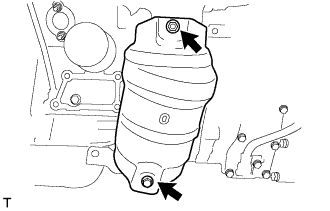
| 17. REMOVE EXHAUST MANIFOLD HEAT INSULATOR NO.2 |
Remove the 2 bolts and manifold heat insulator No.2.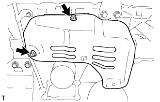
| 18. REMOVE EXHAUST MANIFOLD CONVERTER SUB-ASSEMBLY NO.2 |
Disconnect the heated oxygen sensor connector.
Using several steps, loosen and remove the 6 nuts and bolt in the sequence shown in the illustration.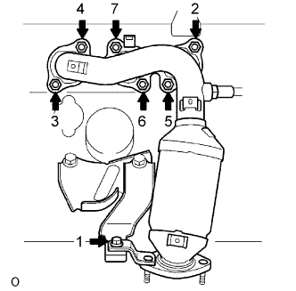
Remove the exhaust manifold converter No.2 and the gasket from the cylinder head LH.
| 19. REMOVE MANIFOLD STAY NO.2 |
Remove the 2 bolts and manifold stay No.2.
| 20. REMOVE ENGINE MOUNTING BRACKET RH |
Remove the 3 bolts and engine mounting bracket RH.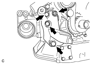
| 21. REMOVE ENGINE MOUNTING STAY BRACKET |
Remove the bolt, nut and engine mounting stay bracket.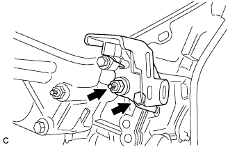
| 22. REMOVE COMPRESSOR MOUNTING BRACKET NO.1 |
Remove the 4 bolts and compressor mounting bracket.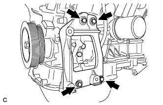
| 23. REMOVE CRANKSHAFT PULLEY |
Using SST, loosen the pulley bolt.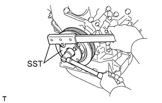
- SST
- 09213-54015
(91651-60855)
09330-00021
Using SST and the pulley bolt, remove the pulley.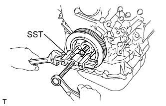
- SST
- 09950-50013
(09951-05010, 09952-05010, 09953-05020, 09954-05031)
- NOTICE:
- Before using SST, apply lubricating oil on the threads and tip of the SST center bolt.
| 24. REMOVE TIMING BELT NO.1 COVER |
Remove the 4 bolts and the timing belt cover No.1.
| 25. REMOVE TIMING BELT NO.2 COVER |
Disconnect the engine wire protector clamps from the timing belt No.2 cover.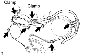
Remove the 5 bolts and the timing belt cover.
| 26. REMOVE ENGINE MOUNTING BRACKET RH |
Remove the 2 bolts, 2 nuts and engine mounting bracket RH.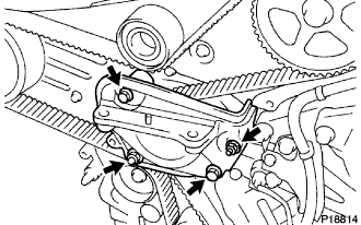
| 27. REMOVE TIMING BELT GUIDE NO.2 |
| 28. REMOVE TIMING BELT |
Set No.1 cylinder to TDC/compression.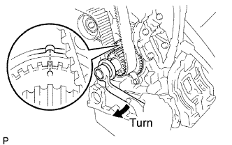
Temporarily install the crankshaft pulley bolt and washer to the crankshaft.
Turn the crankshaft clockwise, and align the timing mark of the crankshaft timing pulley with the oil pump body.
Check that the timing marks of the camshaft timing pulleys and No.3 timing belt cover are aligned.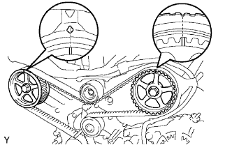
If not, turn the crankshaft 1 revolution (360°).Remove the crankshaft pulley bolt.
If reusing the timing belt, check that there are 3 installation marks on the timing belt as shown in the illustration.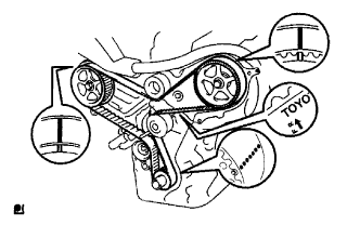
If the installation marks have disappeared, put new installation marks on the timing belt before removing.
Set No.1 cylinder to approximately 60° BTDC/compression.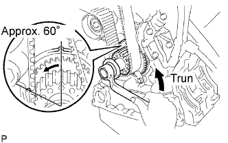
Turn the crankshaft counterclockwise by approximately 60°.
- NOTICE:
- If the timing belt is disengaged, having the crankshaft pulley at the wrong angle can cause the piston head and valve head to come into contact with each other when you remove the camshaft timing pulley and camshaft, causing damage. So always set the crankshaft pulley at the correct angle.
Remove the timing belt tensioner.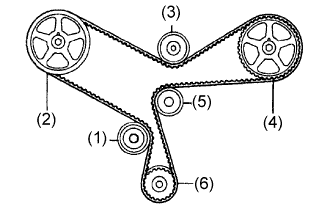
1st
No.1 idler pulley
2nd
RH camshaft timing pulley
3rd
No.2 idler pulley
4th
LH camshaft timing pulley
5th
Water pump pulley
6th
Crankshaft timing pulley
| 29. REMOVE TIMING BELT IDLER SUB-ASSEMBLY NO.1 |
Using a socket hexagon wrench 10 mm, remove the pivot bolt, timing belt idler No.1 and distributor drive gear plate washer.
| 30. REMOVE CRANKSHAFT TIMING PULLEY |
Remove the bolt and the timing belt plate.
Install the pulley bolt to the crankshaft.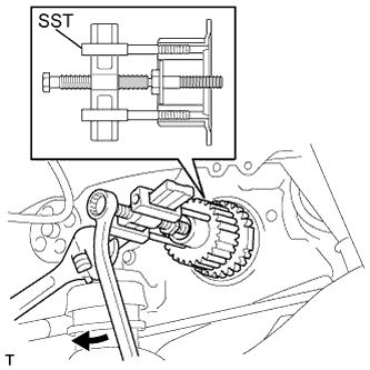
Using SST, remove the crankshaft timing pulley.
- SST
- 09950-50013
(09951-05010, 09952-05010, 09953-05020, 09954-05011)
- NOTICE:
- Do not scratch the sensor part of the crankshaft timing pulley.
- Before using SST, apply lubricating oil to the threads and tip of the center bolt 150.
- Do not scratch the sensor part of the crankshaft timing pulley.
| 31. REMOVE OIL LEVEL GAGE SUB-ASSEMBLY |
Remove the oil level gage sub-assembly from the oil level gage guide.
| 32. REMOVE OIL PAN SUB-ASSEMBLY NO.2 |
Remove the 10 bolts and 2 nuts.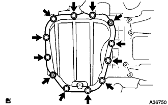
Insert the blade of SST between oil pan No.1 and oil pan No.2, cut off the sealer and remove the oil pan No.2.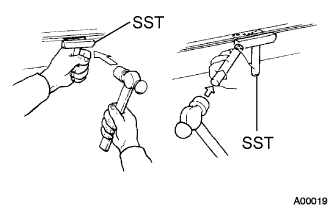
- SST
- 09032-00100
- NOTICE:
- Do not damage the contact surface of oil pan No.1 where oil pan No.2 is mounted.
- Do not damage the flange portion of oil pan No.2 when removing.
- Do not damage the contact surface of oil pan No.1 where oil pan No.2 is mounted.
| 33. REMOVE OIL STRAINER SUB-ASSEMBLY |
Remove the bolt and 2 nuts, and remove the oil strainer and the gasket.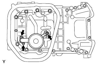
| 34. REMOVE OIL PAN SUB-ASSEMBLY |
Loosen and remove the 17 bolts uniformly.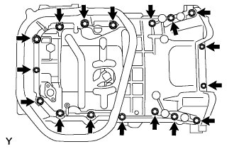
Using a screwdriver, remove the oil pan by prying between the cylinder block and the oil pan.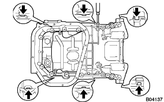
- NOTICE:
- Do not damage the contact surfaces of the oil pan and cylinder block.
| 35. REMOVE CRANK POSITION SENSOR |
Disconnect the crankshaft position sensor connector.
Remove the bolt and the crankshaft position sensor.
| 36. REMOVE OIL PUMP ASSEMBLY |
Remove the 9 bolts.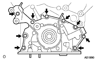
Using a screwdriver, remove the oil pump by prying between the oil pump and the main bearing cap.
Remove the O-ring.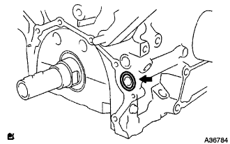
| 37. REMOVE OIL PUMP SEAL |
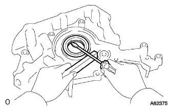
Using a screwdriver, pry out the oil seal.