Main Switch Circuit
Circuit diagnosis
DESCRIPTION
The power back door main switch only turns on while the switch is being pressed, and turns off when the switch is released.The power back door ECU is connected to the power back door main switch via terminals MSW and MSE, and power back door operation cancel request signals are input to the ECU.
The power back door ECU applies voltage to the power back door main switch via terminal MSW. When the switch is on (there is continuity between the switch terminals), a power back door operation cancel request signal is input to the power back door ECU.
- NOTICE:
- The power back door ECU records the back door positions in the memory. In the case where any of the batteries, fuses, power back door ECU and power back door drive unit are removed and then reinstalled, the power back door ECU loses the memory of the door positions. In such a case, resetting the power back door system is necessary. Refer to the resetting operation specified in page Click here.
WIRING DIAGRAM
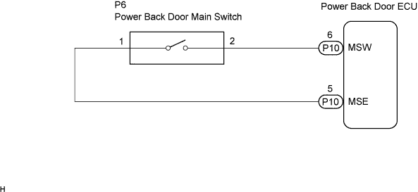

INSPECTION PROCEDURE
| 1. READ VALUE OF DATA LIST |

Check the DATA LIST to ensure proper function of the power back door main switch.
Power Back Door ECU: Item
Measurement Item /
Display (Range)
Normal Condition
Diagnostic Note
PBD Main SW
Power back door main switch signal
/ON or OFF
OFF: Power back door main switch is not pushed
ON: Power back door main switch is pushed
-
- HINT:
- MAIN appears on the display of the intelligent tester, however, the name of the part corresponding to the display of the tester is "power back door main switch".
- OK:
- The display is as specified in the normal condition.
|
|
||||

| OK | ||
 |
||
| ||
| 2. INSPECT POWER BACK DOOR MAIN SWITCH |
Remove the power back door main switch.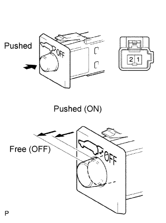
Measure the resistance according to the value(s) in the table below.
- Standard resistance:
Tester Connection
Switch Position
Specified Condition
1 - 2
Free (OFF)
10 kΩ or higher
1 - 2
Pushed (ON)
Below 1 Ω
|
|
||||

| OK | |
 |
| 3. CHECK WIRE HARNESS (POWER BACK DOOR MAIN SWITCH - POWER BACK DOOR ECU) |
Disconnect the power back door main switch connector.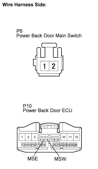
Disconnect the power back door ECU connector.
Measure the resistance according to the value(s) in the table below.
- Standard resistance:
Tester Connection
Condition
Specified Condition
P6-1 - P10-5 (MSE)
Always
Below 1 Ω
P6-2 - P10-6 (MSW)
Always
Below 1 Ω
|
|
||||
| OK | ||
|
||
| ||