Power Back Door Warning Buzzer Circuit
Circuit diagnosis
DESCRIPTION
The power back door ECU applies current from terminal BZR+ to terminal BZR- to activate the power back door warning buzzer.The power back door system uses a warning buzzer built into the back door which has 3 patterns of sounding according to the situation:
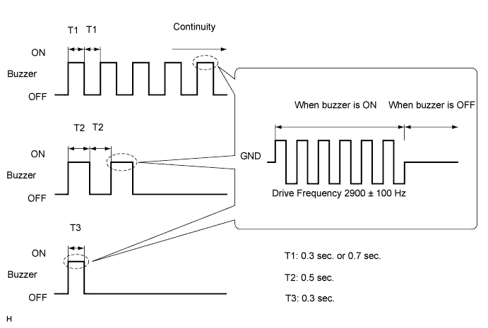
| When all the following conditions are met, the warning buzzer sounds at a cycle of 0.3 seconds: |
- The ignition switch is turned to the ON position.
- The shift lever is moved into any position except P.
- The back door is open or the power back door is activated to open.
The warning buzzer continues to sound until the back door is fully closed or the shift lever is moved into the P position.
| While the power back door is operating, the warning buzzer sounds at a cycle of 0.7 seconds. This stops sounding when the power back door stops. The warning buzzer is set to OFF at factory (default setting) and can be customized when required. |
| When the power back door is activated to open, the warning buzzer that notifies the start of opening sounds at 2 cycles of 0.5 seconds. At the start of opening of the power back door, the wireless buzzer (built into the engine compartment) also sounds. |
| When the direction that the power back door is moving is reversed by switch operation (power back door opener/closer switch, transmitter switch, power back door closer switch or back door opener switch (outside handle switch)) or the activation of the jam protection function during power back door operation, the warning buzzer sounds once for 0.3 seconds. |
- HINT:
- Only item 2 can be customized (Click here).
- If all items occur at the same time, item 1 is prior to the others.
- Only item 2 can be customized (Click here).
- NOTICE:
- The power back door ECU records the back door positions in the memory. In the case where any of the batteries, fuses, power back door ECU and power back door drive unit are removed and reinstalled, the power back door ECU loses the memory of the door positions. In such cases, resetting the power back door system is necessary. Refer to the resetting operation specified in page Click here.
WIRING DIAGRAM
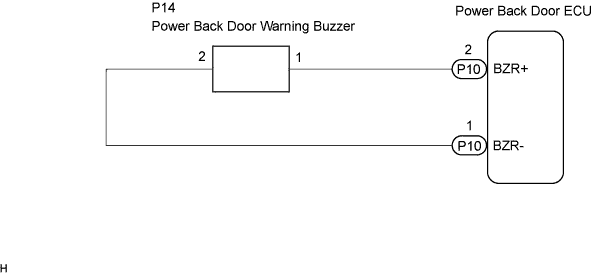

INSPECTION PROCEDURE
| 1. PERFORM ACTIVE TEST BY INTELLIGENT TESTER |

Select the ACTIVE TEST, use the intelligent tester to generate a control command, and then check that the power back door warning buzzer operates.
Power back door ECU: Item
Test Details
Diagnostic Note
PBD Buzzer
Power back door buzzer sound
OFF/ON
Buzzer sounds once for 0.5 sec.
- OK:
- The buzzer sounds normally.
|
|
||||

| OK | ||
 |
||
| ||
| 2. CHECK WIRE HARNESS (POWER BACK DOOR WARNING BUZZER WIRE HARNESS SIDE) |
Remove the back door warning buzzer connector.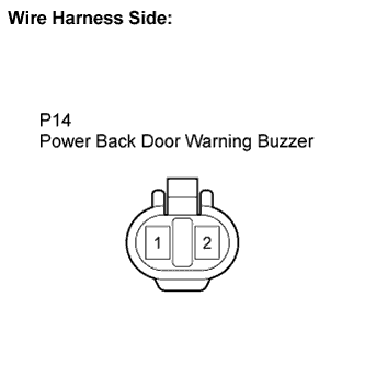
Measure the buzzer connector side voltage.
- HINT:
- Use an oscilloscope to check the output voltages of the buzzer.
OK Tester Connection
Tool Setting
Measurement Condition
Specified Condition
P14-1 - Body ground
5 V/DIV., 500 ms/DIV.
Conditions that cause buzzer to sound are met
(See CIRCUIT DESCRIPTION)
Pulse generation
(See the diagram below)
|
|
||||
| OK | |
 |
| 3. INSPECT POWER BACK DOOR WARNING BUZZER ASSEMBLY |
Remove the power back door warning buzzer assembly.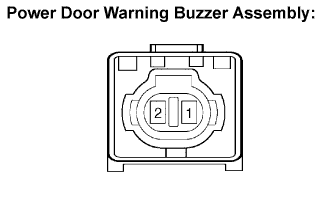
Measure the resistance according to the value(s) in the table below.
- Standard resistance:
Tester Connection
Specified Condition
1 - 2
Approx. 1 kΩ
- NOTICE:
- Directly applying battery voltage to the buzzer does not cause the buzzer to sound.
|
|
||||

| OK | |
|
| 4. CHECK WIRE HARNESS (POWER BACK DOOR WARNING BUZZER - POWER BACK DOOR ECU) |
Disconnect the power back door warning buzzer connector.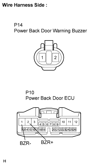
Disconnect the power back door ECU connector.
Measure the resistance according to the value(s) in the table below.
- Standard resistance:
Tester Connection
Condition
Specified Condition
P14-1 - P10-2 (BZR+)
Always
Below 1 Ω
P14-2 - P10-1 (BZR-)
Always
Below 1 Ω
|
|
||||
| OK | ||
|
||
| ||