Back-up Light Circuit
Circuit diagnosis
DESCRIPTION
The HV control ECU receives shift position R signal and controls the back-up light relay. The back-up light relay installed in the power distributor.System diagram of the power distributor (Click here).
System description of the power distributor (Click here).
WIRING DIAGRAM
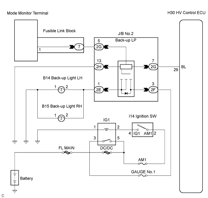

INSPECTION PROCEDURE
| 1. CHECK HARNESS AND CONNECTOR (POWER SOURCE CIRCUIT) |

Disconnect the connector from the J/B No.2 (power distributor).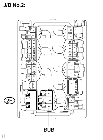
Measure the voltage according to the value(s) in the table below.
- Voltage:
Tester connection
Condition
Specified value
BUB (2F-3) - Body ground
Ignition switch ON
10 to 14 V
BUB (2F-3) - Body ground
Ignition switch OFF
Below 1 V
|
|
||||

| OK | |
 |
| 2. CHECK MODE MONITOR TERMINAL (BACK-UP RELAY) |
Preparation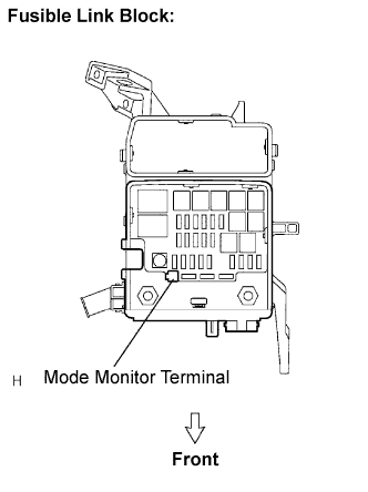
Connect the connector.
Remove the cover of the fusible link block assembly.
Set the vehicle to the following condition.
- Ignition switch ON.
- Shift in R position.
- Ignition switch ON.
Check voltage
Measure the voltage between the Mode Monitor Terminal and body ground.
- Voltage:
Result
Proceed to
0 V or Approx. 12 V
A
Approx. 6.2 V
B
Approx. 2.0 V
C
|
|
||||
|
|
||||

| A | |
|
| 3. CHECK HARNESS AND CONNECTOR (J/B NO. 2 - MODE MONITOR TERMINAL) |
Disconnect the 2G connector from the J/B No.2.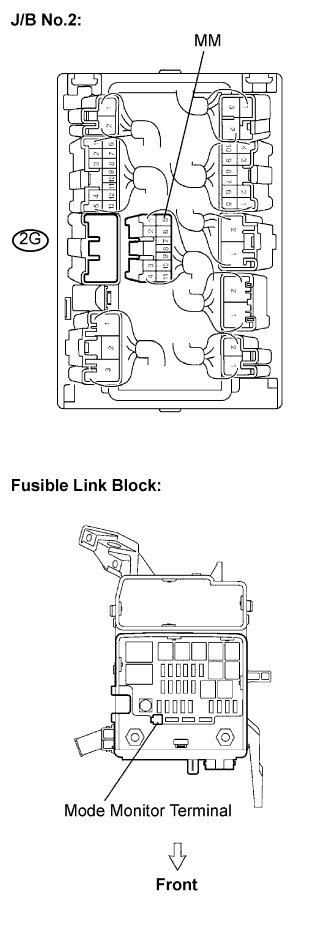
Measure the resistance according to the value(s) in the table below.
- Resistance:
Tester connection
Condition
Specified value
2G-5 - Mode monitor terminal
Always
Below 1 Ω
2G-5 - Body ground
Always
10 kΩ or higher
|
|
||||
| OK | |
|
| 4. CHECK HARNESS AND CONNECTOR (J/B NO.2 - BODY GROUND) |
Disconnect the connector from the J/B No.2.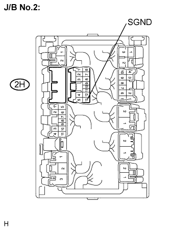
Measure the resistance according to the value(s) in the table below.
- Resistance:
Tester connection
Condition
Specified value
2H-13 (SGND) - Body ground
Always
Below 1 Ω
|
|
||||
| OK | |
|
| 5. INSPECT JUNCTION BLOCK NO.2 (BACK-UP RELAY) |
Turn the ignition switch to OFF position.
Remove the J/B No.2.
Inspect the back-up relay.
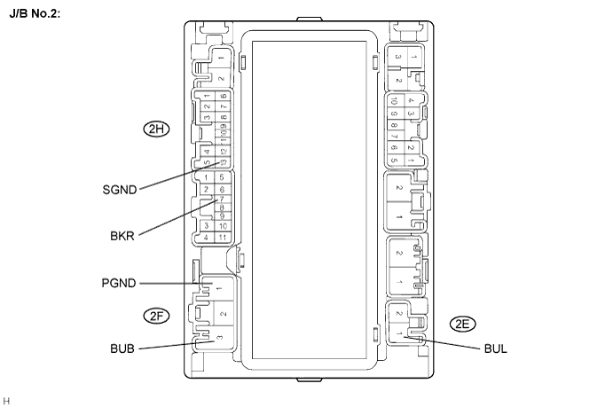
Connect the positive battery lead to terminal BUB of the J/B No.2 and the negative lead to terminal SGND, PGND.
Symbols (terminals No.)
Connection
BUB (2F-3) - SGND (2H-13), PGND (2F-1)
Positive - Negative
Measure the voltage according to the value(s) in the table below.
- Voltage:
Tester Connection
Specified Condition
BUL (2E-1) - SGND (2H-13)
0 V
Connect the battery positive lead to terminal BKR of the J/B No.2.
Symbols (terminals No.)
Connection
BKR (2G-7)
Positive
Measure the voltage according to the value(s) in the table below.
- Voltage:
Tester Connection
Specified Condition
BUL (2E-1) - SGND (2H-13)
10 to 14 V
|
|
||||
| OK | |
|
| 6. CHECK HARNESS AND CONNECTOR (J/B NO. 2 - HV CONTROL ECU) |
Disconnect the connector from the J/B No.2 (power distributor) and HV control ECU.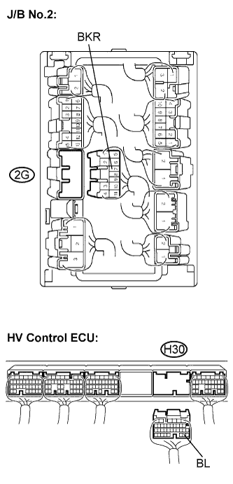
Measure the resistance according to the value(s) in the table below.
- Resistance:
Tester connection
Condition
Specified value
2G-7 (BKR) - H30-29 (BL)
Always
Below 1 Ω
2G-7 (BKR) - Body ground
Always
10 kΩ or higher
|
|
||||
| OK | |
|
| 7. CHECK HARNESS AND CONNECTOR (J/B NO. 2 - BULB) |
Disconnect the connectors from the J/B No.2 (power distributor) and back-up light bulbs.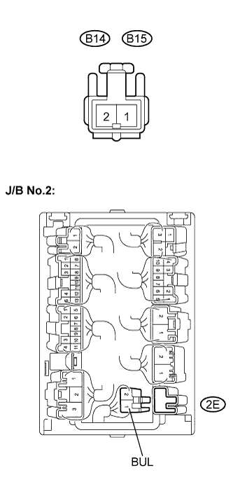
Measure the resistance according to the value(s) in the table below.
- Resistance:
Tester connection
Condition
Specified value
2E-1 (BUL) - B14-2 (Back-up light LH)
Always
Below 1 Ω
2E-1 (BUL) - B15-2 (Back-up light RH)
Always
Below 1 Ω
2E-1 (BUL)- Body ground
Always
10 kΩ or higher
|
|
||||
| OK | |
|
| 8. CHECK HARNESS AND CONNECTOR (BULB - BODY GROUND) |
Measure the resistance according to the value(s) in the table below.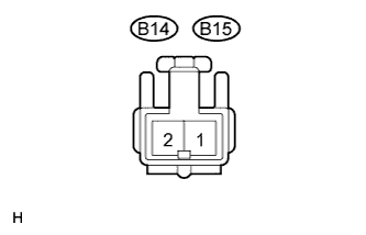
- Resistance:
Tester connection
Condition
Specified value
B14-1 (Back-up light LH) - Body ground
Always
Below 1 Ω
B15-1 (Back-up light RH) - Body ground
Always
Below 1 Ω
|
|
||||
| OK | ||
 |
||
| ||
| 9. CHECK HARNESS AND CONNECTOR (SHORT CIRCUIT DRIVEN SIDE BY RELAY) |
Preparation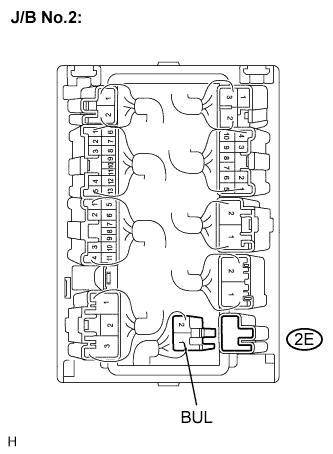
For easier disconnection, remove the J/B No.2 and then take apart the connectors.
Disconnect only the connector "2E" .
Check voltage
Measure the voltage between the Mode Monitor Terminal and body ground.
- Voltage:
Result
Proceed to
Approx. 6.2 V
A
Approx. 2.0 V
B
|
|
||||
| A | ||
|
||
| ||