REMOVAL
Removal / installation
| 1. DISCHARGE FUEL SYSTEM PRESSURE |

| 2. DISCONNECT CABLE FROM NEGATIVE BATTERY TERMINAL |
| 3. REMOVE EXHAUST PIPE ASSEMBLY CENTER |
| 4. REMOVE FRONT FLOOR HEAT INSULATOR NO.3 |
Remove the 5 nuts and front floor heat insulator No.3.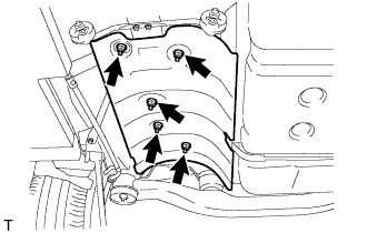

| 5. REMOVE FUEL TANK PROTECTOR SUB-ASSEMBLY NO.1 |
Disengage the 4 grommets.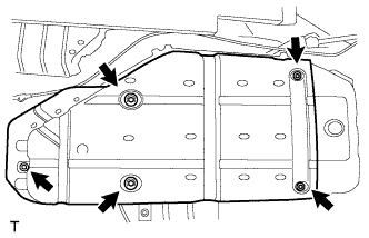
Remove the screw and fuel tank protector sub-assembly No.1.
| 6. SEPARATE PARKING BRAKE CABLE ASSEMBLY NO.3 |
Remove the nut and disconnect the parking brake cable assembly No.3.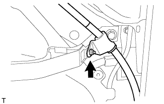
| 7. DISCONNECT FUEL TANK WIRE |
Separate the fuel tank wire connector from the bracket.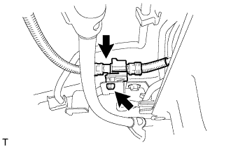
Disconnect the connector.
| 8. REMOVE CHARCOAL CANISTER PROTECTOR |
Remove the 3 bolts and charcoal canister protector.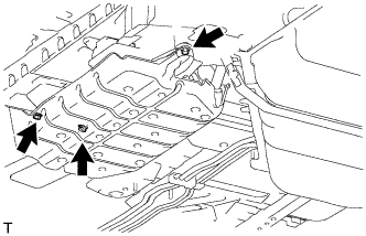
| 9. DISCONNECT FUEL TANK TO CANISTER TUBE SUB-ASSEMBLY |
Disconnect the fuel tank to canister tube sub-assembly from the charcoal canister assembly.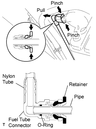
Pinch the tube connector and then pull out the fuel tank to canister tube sub-assembly.
- NOTICE:
- Check for dirt or other foreign objects around the connector before this operation. Clean the connector as necessary.
- Be careful not to allow mud or foreign matter to scratch or come into contact with the pipe and connector that are sealed by an O-ring.
- Do not use any tools for this operation.
- Do not damage the disconnected pipe and connector. Prevent intrusion of foreign objects by covering the pipe and connector with a plastic bag.
- When the pipe and connector are stuck, push and pull the connector to release. Pull out the connector carefully.
- Check for dirt or other foreign objects around the connector before this operation. Clean the connector as necessary.
Separate the fuel tank to canister tube from the clamp.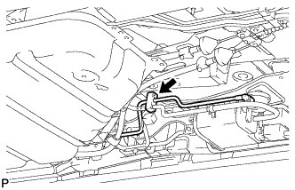
| 10. DISCONNECT FUEL TANK MAIN TUBE SUB-ASSEMBLY |
Pinch the tabs of the retainer to disengage the lock claws and pull the retainer down as shown in the illustration.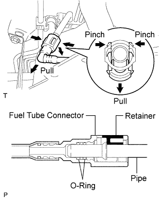
Pull out the fuel tank main tube.
- NOTICE:
- Check for dirt or other foreign objects around the connector before this operation. Clean the connector as necessary.
- Be careful not to allow mud or foreign matter to scratch or come into contact with the pipe and connector that are sealed by O-rings.
- Do not use any tools for this operation.
- Do not damage the disconnected pipe and connector. Prevent intrusion of foreign objects by covering the pipe and connector with a plastic bag.
- When the pipe and connector are stuck, push and pull the connector to release. Pull out the connector carefully.
- Check for dirt or other foreign objects around the connector before this operation. Clean the connector as necessary.
| 11. DISCONNECT FUEL TANK TO FILLER PIPE HOSE |
Loosen the hose clamp bolt and disconnect the fuel tank to filler pipe hose.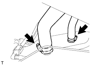
Loosen the hose clamp bolt and disconnect the fuel tank breather hose.
| 12. REMOVE FUEL TANK ASSEMBLY |
Set a transmission jack to the fuel tank.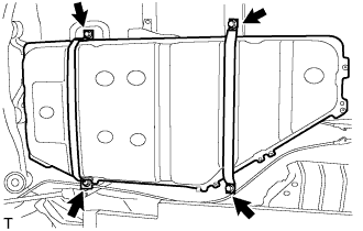
Remove the 4 bolts and the fuel tank bands.
Operate the transmission jack, and remove the fuel tank.
| 13. REMOVE FUEL PUMP AND GAUGE WITH SUCTION TUBE |
Disconnect the fuel pump connector.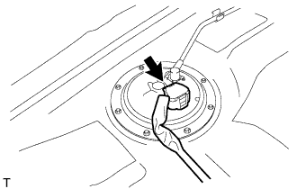
Remove the tube joint clip and clamp, and pull out the fuel pump tube.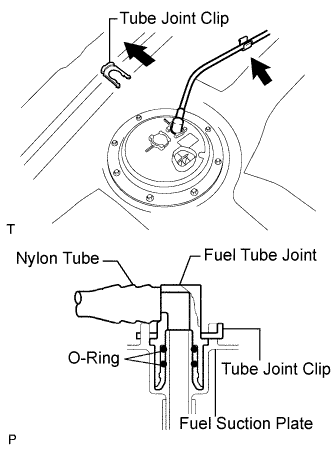
- NOTICE:
- Check that there is no dirt or foreign matter around the fuel tube joint. After cleaning off any dirt, proceed with the work.
- Be careful not to allow dirt or foreign matter to scratch or come into contact with the fuel tube connector and fuel suction plate that are sealed by O-rings.
- Do not use any tools for this work.
- Do not bend or twist the nylon tube by force.
- Cover the disconnected fuel tube joint with a plastic bag.
- When the fuel tube joint and fuel suction plate are stuck, pinch the fuel tank tube with your fingers, and turn it carefully to release. Disconnect the fuel tank tube.
- Check that there is no dirt or foreign matter around the fuel tube joint. After cleaning off any dirt, proceed with the work.
Remove the 8 bolts and fuel tank vent tube set plate.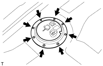
Pull out the fuel pump assembly from the fuel tank.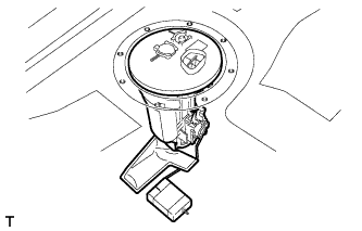
- NOTICE:
- Do not damage the fuel pump filter.
- Be careful not to bend the arm of the sender gauge.
- Do not damage the fuel pump filter.
Remove the gasket from the fuel suction tube.
| 14. REMOVE FUEL SENDER GAUGE ASSEMBLY |
Disconnect the fuel sender gauge connector.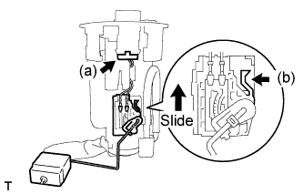
Unlock the fuel sender gauge, then slide and remove it.
| 15. REMOVE FUEL SUCTION PLATE SUB-ASSEMBLY |
Disconnect the fuel pump connector.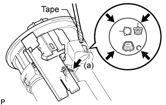
Using a screwdriver with its tip wrapped with tape, disengage the 4 snap claws through the claw holes, and pull out the fuel suction plate.
- NOTICE:
- Do not damage the fuel suction support.
| 16. REMOVE FUEL PUMP HARNESS |
Disconnect the connector.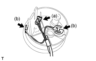
Using a screwdriver, pry out the fuel pump harness.
| 17. REMOVE FUEL SUCTION SUPPORT NO.2 |
Using a screwdriver with its tip wrapped with tape, disengage the 4 snap claws through the claw holes, and remove the fuel suction support.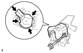
- NOTICE:
- Do not damage the fuel suction support.
| 18. REMOVE FUEL PUMP CUSHION RUBBER |
Remove the fuel pump cushion rubber from the fuel pump.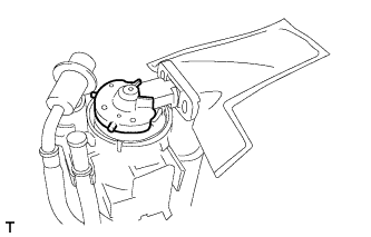
| 19. REMOVE FUEL PUMP AND FUEL FILTER ASSEMBLY |
Pull out the fuel pump from the fuel tank fuel filter.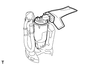
| 20. REMOVE FUEL PRESSURE WITH JET PUMP REGULATOR ASSEMBLY |
Remove the fuel pressure with jet pump regulator assembly from the fuel tank fuel filter.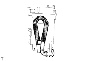
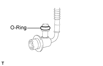
Remove the O-ring from the fuel pressure with jet pump regulator assembly.