B2602 The multiplex tilt & telescopic ECU receives a key unlock warning switch ON signal after receiving an...
Diagnostic trouble codes
DESCRIPTION
A signal (ON or OFF) is sent from the driver side J/B ECU to the multiplex tilt & telescopic ECU via the communication bus when the ignition key is inserted into the key cylinder. The multiplex tilt & telescopic ECU uses this signal to operate the auto away or auto return function.| DTC No. |
Detection Item |
Trouble Area |
| B2602 |
|
|
WIRING DIAGRAM
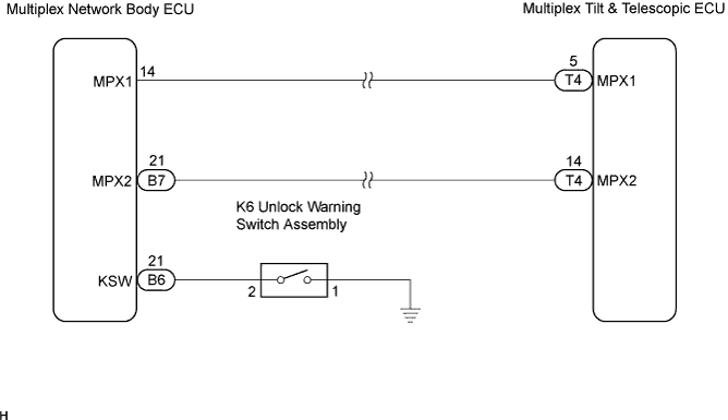

INSPECTION PROCEDURE
| 1. CHECK OTHER DTC OUTPUT |

- HINT:
- The power tilt & telescopic steering column system uses the multiplex communication system, so check its diagnostic system before proceeding to troubleshooting.
Check if the power tilt & telescopic steering column system DTC B2621 is output.
- Result:
DTC Condition
Proceed to
No output
A
B2621 is output
B
- HINT:
- If DTC B2621 besides B2602 is output, perform troubleshooting for this DTC first.
- DTC B2621 indicates a communication interruption.
- If DTC B2621 besides B2602 is output, perform troubleshooting for this DTC first.
|
|
||||

| A | |
 |
| 2. READ VALUE OF INTELLIGENT TESTER |
Connect the intelligent tester to the DLC3.
Turn the ignition switch to the ON position and turn the intelligent tester on.
Select "Tilt & Telescopic".
Touch the "Data List" button.
Select "Key Switch (MPX)".
Check the communication state on the tester screen.
- TILT & TELESCOPIC:
Item
Measurement Item/Range (Display)
Normal Condition
Key Switch (MPX)
Communication state of unlock warning switch/ON or OFF
ON: Communication is normal
OFF: Communication is interrupted
- OK:
- "ON" is displayed.
|
|
||||
| NG | |
|
| 3. INSPECT UNLOCK WARNING SWITCH ASSEMBLY |
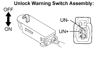 |
Disconnect the K6 connector from the unlock warning switch assembly.
Measure the resistance according to the value(s) in the table below.
- Resistance:
Tester Connection (Terminal No.)
Condition
Specified Condition
UN+ (2) - UN- (1)
Unlock warning switch OFF (Ignition key is removed)
10 kΩ or higher
UN+ (2) - UN- (1)
Unlock warning switch ON (Ignition key is inserted)
Below 1 Ω
|
|
||||
| OK | |
|
| 4. CHECK HARNESS AND CONNECTOR (BETWEEN BODY ECU AND UNLOCK WARNING SWITCH ASSEMBLY) |
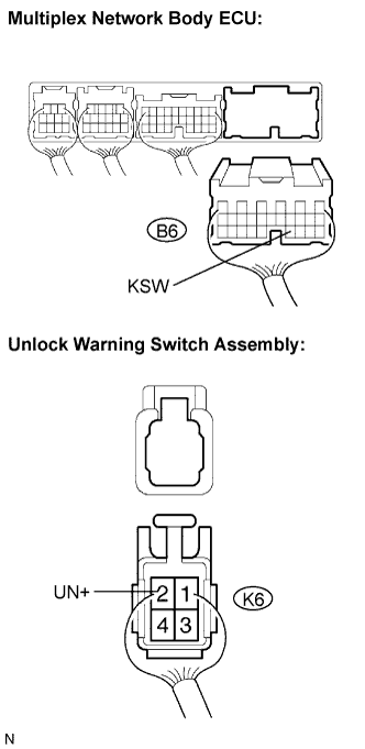 |
Disconnect the B6 connector from the multiplex network body ECU.
Measure the resistance according to the value(s) in the table below.
- Resistance:
Tester Connection (Terminal No.)
Condition
Specified Condition
KSW (B6-21) - UN+ (K6-2)
Always
Below 1 Ω
KSW (B6-21) - Body ground
Always
10 kΩ or higher
|
|
||||
| OK | |
|
| 5. CHECK HARNESS AND CONNECTOR (BETWEEN UNLOCK WARNING SWITCH ASSEMBLY AND BODY GROUND) |
Measure the resistance according to the value(s) in the table below.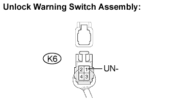
- Resistance:
Tester connection (Terminal No.)
Condition
Specified value
UN- (K6-1) - Body ground
Always
Below 1 Ω
|
|
||||
| OK | ||
 |
||
| ||