B2603 Abnormal voltage value, which is not within the specification, is input to the multiplex tilt & telescopic...
Diagnostic trouble codes
DESCRIPTION
Different voltage values are input to the multiplex tilt & telescopic ECU by operating the manual switch. The multiplex tilt & telescopic ECU then judges which motor and in which direction that motor should be moved based on the voltage value.| DTC No. |
Detection Item |
Trouble Area |
| B2603 |
Abnormal voltage value, which is not within the specification, is input to the multiplex tilt & telescopic ECU when being operated by the manual switch. |
|
WIRING DIAGRAM
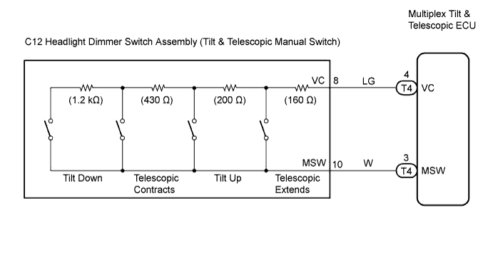

INSPECTION PROCEDURE
| 1. READ VALUE OF INTELLIGENT TESTER |

Connect the intelligent tester to the DLC3.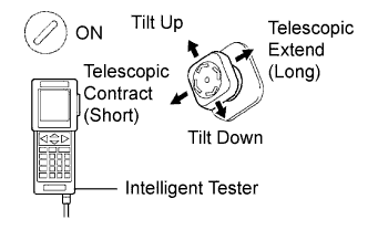
Turn the ignition switch to the ON position and turn on the intelligent tester.
Select "Tilt & Telescopic".
Touch the "Data List" button.
Select "T & T Manual SW Data".
Read voltages on the tester screen when operating the manual switch.
- Voltage:
Manual switch position
Specified value
Neutral
Below 0.2 V
Tilt up
1.67 to 2.13 V
Tilt down
0.54 to 0.74 V
Telescopic contract
1.08 to 1.40 V
Telescopic extend
2.22 to 2.77 V
- Result:
Proceed to
Result
A
Switch voltages in all directions are within the standard.
B
Switch voltages in certain directions are outside the standard.
C
Switch voltages in all directions are outside the standard.
|
|
||||
|
|
||||

| C | |
 |
| 2. CHECK HARNESS AND CONNECTOR (BETWEEN TILT & TELESCOPIC ECU AND TILT & TELESCOPIC SWITCH) |
Disconnect the T4 connector from the multiplex tilt & telescopic ECU.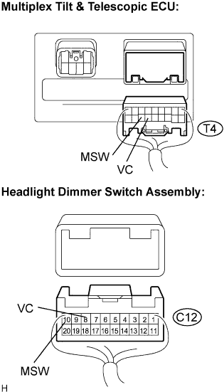
Disconnect the C12 connector from the headlight dimmer switch assembly.
Measure the resistance according to the value(s) in the table below.
- Resistance:
Tester connection
(Terminal No.)
Condition
Specified value
VC (T4-4) - VC (C12-8)
Always
Below 1 Ω
MSW (T4-3) - MSW (C12-10)
Always
Below 1 Ω
VC (C12-8) - Body ground
Always
10 kΩ or higher
MSW (C12-10) - Body ground
Always
10 kΩ or higher
|
|
||||
| OK | |
|
| 3. INSPECT MULTIPLEX TILT & TELESCOPIC ECU (VC TERMINAL VOLTAGE) |
Reconnect the T4 connector to the multiplex tilt & telescopic ECU.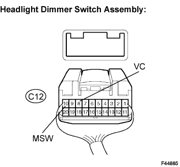
Measure the voltage according to the value(s) in the table below.
- Voltage:
Tester connection
(Terminal No.)
Condition
Specified value
VC (C12-8) - MSW (C12-10)
IG switch ON
4.9 to 5.1 V
|
|
||||
| OK | |
|
| 4. INSPECT HEADLIGHT DIMMER SWITCH ASSEMBLY (TILT & TELESCOPIC MANUAL SWITCH) |
Measure the resistance according to the value(s) in the table below.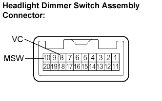
- Resistance:
Tester connection
Condition
(Manual switch position)
Specified value
VC - MSW
Tilt up
360 Ω
Tilt down
1,990 Ω
Telescopic contract
790 Ω
Telescopic extend
160 Ω
|
|
||||
| OK | ||
 |
||
| ||