TERMINALS OF ECU
System information
| TELEVISION CAMERA ASSEMBLY |
Disconnect the T14 camera connector.


Measure the voltage and resistance of each terminal of the wire harness side connector.
If the result is not as specified, there may be a malfunction on the wire harness side.Standard: Symbols (Terminal No.)
Wiring Color
Terminal Description
Condition
Specified value
CGND (T14-3) - Body ground
W - Body ground
Power ground
Always
Below 1 Ω
CB+ (T14-4) - CGND (T14-3)
B - W
Power source
IG switch ON, shift lever R position
Approx. 6 V
Reconnect the T14 camera connector.
Measure the voltage and frequency of each terminal of the connector.
If the result is not as specified, the camera may have a malfunction.Standard: Symbols (Terminal No.)
Wiring Color
Terminal Description
Condition
Specified value
CV+ (T14-2) - CV- (T14-1)
R - Shielded
Display signal
IG switch ON, shift lever R position
See waveform 1
Reference: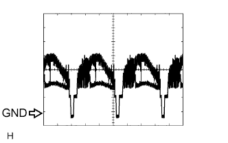
Oscilloscope waveformWaveform 1
Item
Content
Measure terminal
CV+ - CV-
Measure set
0.2 V/DIV, 0.2 μS/DIV
Condition
Ignition switch: ON, Shift lever: R position
| TELEVISION CAMERA ECU |
Disconnect the T15, T16 and T17 ECU connector.
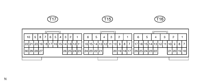
Measure the voltage and resistance of each terminal of the wire harness side connector.
Standard: Symbols (Terminal No.)
Wiring Color
Terminal Description
Condition
Specified value
TX+ (T15-17) - Body ground
GR - Body ground
AVC-LAN control bus
Always
10 kΩ or higher
TX- (T15-18) - Body ground
B - Body ground
AVC-LAN control bus
Always
10 kΩ or higher
TX1- (T15-23) - Body ground
Y - Body ground
AVC-LAN control bus
Always
10 kΩ or higher
TX1+ (T15-24) - Body ground
R - Body ground
AVC-LAN control bus
Always
10 kΩ or higher
+B (T16-1) - GND1 (T16-6)
L - W-B
Battery Supply
Always
10 to 14 V
IG (T16-2) - GND1 (T16-6)
B - W-B (*1)
GR - W-B (*2)
IG signal input
IG switch ON
10 to 14 V
ACC (T16-3) - GND1 (T16-6)
P - W-B
ACC signal input
IG switch ON or ACC
10 to 14 V
GND1 (T16-6) - Body ground
W-B - Body ground
Power ground
Always
Below 1 Ω
CANL (T17-17) - Body ground
Y - Body ground
CAN control bus
Always
10 kΩ or higher
CANH (T17-18) - Body ground
R - Body ground
CAN control bus
Always
10 kΩ or higher
- *1: LHD
- *2: RHD
- *1: LHD
Reconnect the T15, T16 and T17 ECU connector.
Measure the voltage and frequency of each terminal of the connector.
If the result is not as specified, the television camera ECU may have a malfunction.Standard: Symbols (Terminal No.)
Wiring Color
Terminal Description
Condition
Specified value
VG (T15-7) - GND1 (T16-6)
Shielded - W-B
Display signal output ground (Shielded)
Always
Below 1 Ω
R (T15-8) - GND1 (T16-6)
G - W-B
Display signal output (Red)
While displaying map or back monitor
See waveform 2
G (T15-9) - GND1 (T16-6)
W - W-B
Display signal output (Green)
While displaying map or back monitor
See waveform 2
B (T15-10) - GND1 (T16-6)
R - W-B
Display signal output (Blue)
While displaying map or back monitor
See waveform 2
B1 (T15-13) - GND1 (T16-6)
R - W-B
Display signal input (Blue)
While displaying map
See waveform 2
G1 (T15-14) - GND1 (T16-6)
W - W-B
Display signal input (Green)
While displaying map
See waveform 2
R1 (T15-15) - GND1 (T16-6)
G - W-B
Display signal input (Red)
While displaying map
See waveform 2
VG1 (T15-16) - GND1 (T16-6)
Shielded - W-B
Display signal input ground (Shielded)
Always
Below 1 Ω
SYNC (T15-19) - GND1 (T16-6)
B - W-B
Synchronized signal output
While displaying map or back monitor
See waveform 3
VR (T15-20) - GND1 (T16-6)
Y - W-B
Display signal output ground
Always
Below 1 Ω
VR1 (T15-21) - GND1 (T16-6)
Y - W-B
Display signal input ground
Always
Below 1 Ω
SYN1 (T15-22) - GND1 (T16-6)
B - W-B
Synchronized signal input
While displaying map
See waveform 3
CGND (T17-21) - GND1 (T16-6)
W - W-B
Television camera ground
Always
Below 1 Ω
CB+ (T17-22) - GND1 (T16-6)
B - W-B
Power source to television camera
IG switch ON, shift lever R position
Approx. 6 V
CV- (T17-29) - GND1 (T16-6)
Shielded - W-B
Television camera ground (Shielded)
Always
Below 1 Ω
CV+ (T17-30) - GND1 (T16-6)
R - W-B
Display signal of television camera input
IG switch ON, shift lever R position
See waveform 1
Reference:
Oscilloscope waveformWaveform 1
Item
Content
Measure terminal
CV+ - GND1
Measure set
0.2 V/DIV, 0.2 μS/DIV
Condition
Ignition switch: ON, Shift lever: R position
Waveform 2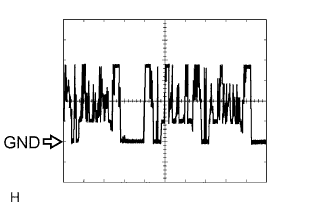
Item
Content
Terminal
R, G, B, R1, G1, B1, - GND1
Measure set
200 mV/DIV, 10 μS/DIV
Condition
Image is being displayed (Parking assist system or navigation system).
Waveform 3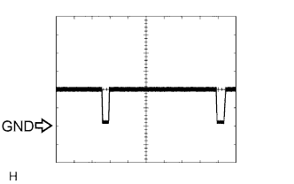
Item
Content
Terminal
SYNC, SYN1 - GND1
Measure set
500 mV/DIV, 10 μS/DIV
Condition
Image is being displayed (Parking assist system or navigation system).