Seat Belt Warning Light for Passenger Seat does not Operate
Circuit diagnosis
DESCRIPTION
w/o Navigation system:When the ignition switch is turned to the ON position, the occupant detection sensor transmits front seat inner belt status to the center integration panel via the combination meter. If the front passenger seat belt is not fastened when the seat is occupied, the warning light on the center integration panel blinks. If the seat belt is fastened, the warning light will turn off.
w/ Navigation system:
When the ignition switch is turned to the ON position, the occupant detection sensor transmits front seat inner belt status to the multi-display via the combination meter. If the front passenger seat belt is not fastened when the seat is occupied, the warning light on the multi-display blinks. If the seat belt is fastened, the warning light will turn off.
WIRING DIAGRAM
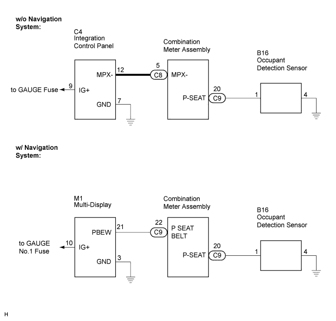

INSPECTION PROCEDURE
| 1. PERFORM ACTIVE TEST USING INTELLIGENT TESTER |

Operate the intelligent tester according to the steps on the display and select "ACTIVE TEST".
- COMBINATION METER:
Item
Test Details
Diagnostic Note
P-BELT REMIND
P-SEAT BELT indicator light (OFF/ON)
-
- OK:
- Switch condition (ON/OFF) can be switched by "ACTIVE TEST".
|
|
||||

| OK | |
 |
| 2. SYSTEM CHECK |
System check
| w/o Navigation system |
B |
| w/ Navigation system |
A |
|
|
||||

| A | |
|
| 3. INSPECT MULTI-DISPLAY |
Disconnect the M1 connector.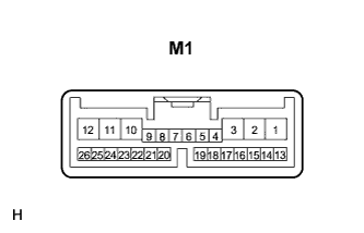
Measure the voltage according to the value(s) in the table below.
- Standard voltage:
Tester Connection
Condition
Specified Condition
M1-10 (IG+) - Body ground
Ignition switch ON
10 to 14 V
M1-21 (PBEW) - Body ground
Ignition switch ON, sit on the front passenger seat, seat belt warning light OFF→ Blinks
10 to 14 V → Below 1 V
- Standard resistance:
Tester Connection
Condition
Specified Condition
M1-3 (GND) - Body ground
Always
Below 1 Ω
|
|
||||
| OK | |
|
| 4. INSPECT COMBINATION METER ASSEMBLY |
Disconnect the C9 connector.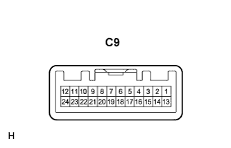
Measure the resistance according to the value(s) in the table below.
- Standard resistance:
Tester Connection
Condition
Specified Condition
C9-20 (P-SEAT) - Body ground
Ignition switch ON, sit on the front passenger seat, seat belt is unfastened → Fastened
10 kΩ or higher → Below 1 Ω
|
|
||||
| OK | |
|
| 5. CHECK WIRE HARNESS (COMBINATION METER ASSEMBLY - MULTI-DISPLAY) |
Disconnect the C9 and M1 connectors.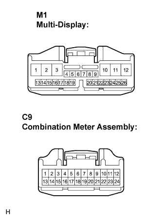
Measure the resistance according to the value(s) in the table below.
- Standard resistance:
Tester Connection
Condition
Specified Condition
C9-22 (P SEAT BELT) - M1-21 (PBEW)
Always
Below 1 Ω
|
|
||||
| OK | ||
 |
||
| ||
| 6. CHECK WIRE HARNESS (COMBINATION METER ASSEMBLY - OCCUPANT DETECTION SENSOR) |
Disconnect the C9 and B16 connectors.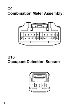
Measure the resistance according to the value(s) in the table below.
- Standard resistance:
Tester Connection
Condition
Specified Condition
C9-20 (P-SEAT) - B16-1
Always
Below 1 Ω
|
|
||||
| OK | ||
|
||
| ||
| 7. CHECK INTEGRATION CONTROL & PANEL |
Disconnect the C4 connector.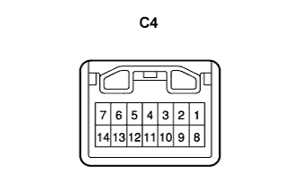
Measure the voltage and resistance according to the value(s) in the table below.
- Standard voltage:
Tester Connection
Condition
Specified Condition
C4-9 (IG) - Body ground
Ignition switch ON
10 to 14 V
- Standard resistance:
Tester Connection
Condition
Specified Condition
C4-7 (GND) - Body ground
Always
Below 1 Ω
|
|
||||
| OK | |
|
| 8. CHECK WIRE HARNESS (COMBINATION METER ASSEMBLY - OCCUPANT DETECTION SENSOR) |
Disconnect the C9 and B16 connectors.
Measure the resistance according to the value(s) in the table below.
- Standard resistance:
Tester Connection
Condition
Specified Condition
C9-20 (P-SEAT) - B16-1
Always
Below 1 Ω
|
|
||||
| OK | ||
|
||
| ||