REASSEMBLY
Removal / installation
| 1. INSTALL FRONT PASSENGER AIRBAG ASSEMBLY |
| 2. INSTALL AUTOMATIC LIGHT CONTROL SENSOR |
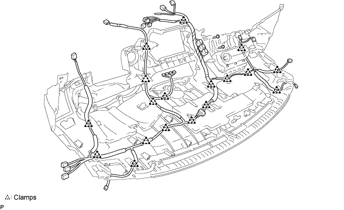
| 3. INSTALL INSTRUMENT PANEL NO.2 WIRE |

Engage the 18 clamps.
Install the 2 screws and the instrument panel No.2 wire.

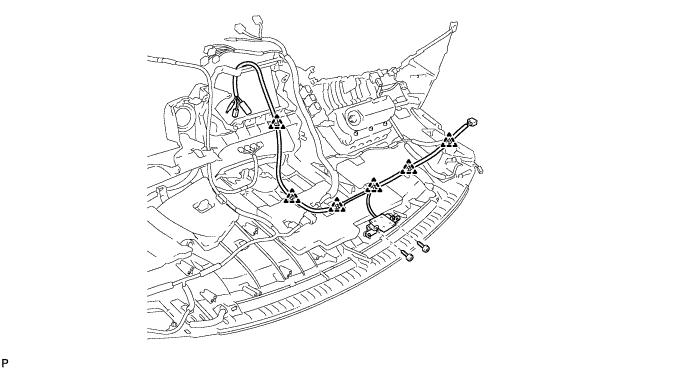
| 4. INSTALL NO.2 RADIO ANTENNA CORD (w/ Navigation System) |
Engage the 6 clamps and install the No.2 radio antenna cord .
Install the navigation antenna with the 2 screws.
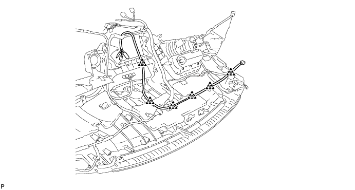
| 5. INSTALL NO.2 RADIO ANTENNA CORD (w/o Navigation System) |
Engage the 6 clamps and install the No.2 radio antenna cord.
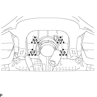
| 6. INSTALL GLOVE BOX LIGHT ASSEMBLY |
Engage the 2 claws and install the glove box light assembly.
Connect the connector.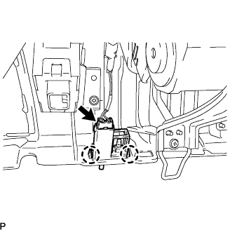
| 7. INSTALL INSTRUMENT PANEL BRACKET SUB-ASSEMBLY CENTER |
Install the screw <C> and the instrument panel bracket sub-assembly center.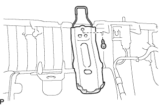
| 8. INSTALL DEFROSTER NOZZLE NO.1 GARNISH |
Engage the 2 clips and 4 claws, then install the defroster nozzle No.1 garnish.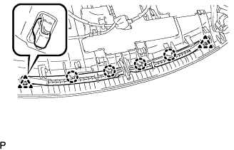
| 9. INSTALL NETWORK GATEWAY ECU |
Install the screw <C> and the network gateway ECU.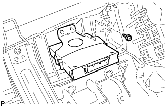
| 10. INSTALL DOOR OPENING RELAY ASSEMBLY |
Install the screw <C> and the door opening relay assembly.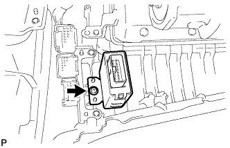
| 11. INSTALL WINDSHIELD WIPER RELAY ASSEMBLY (w/ Rain Sensor) |
Install the screw <C> and the windshield wiper relay assembly.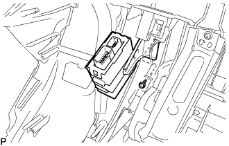
| 12. INSTALL SIDE DEFROSTER NO.1 NOZZLE |
Engage the 2 claws and install the side defroster No.1 nozzle.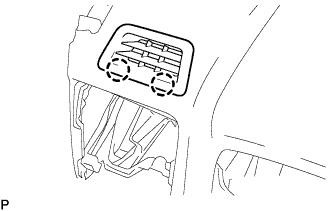
| 13. INSTALL SIDE DEFROSTER NO.2 NOZZLE |
- HINT:
- Use the same procedures for the side defroster No.2 nozzle and the side defroster No.1 nozzle.
| 14. INSTALL SIDE DEFROSTER NOZZLE NO.1 DUCT |
Install the screw <C> and the side defroster No.1 nozzle duct.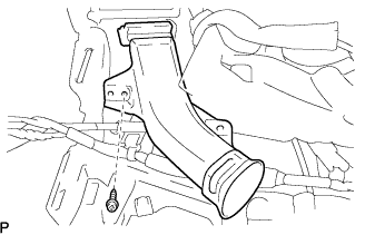
| 15. INSTALL SIDE DEFROSTER NOZZLE NO.2 DUCT |
- HINT:
- Use the same procedures for the side defroster No.2 nozzle duct and the side defroster No.1 nozzle duct.
| 16. INSTALL HEATER TO REGISTER CENTER SUB DUCT |
Install the 2 screws <C> and the heater to register center sub duct.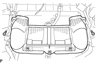
| 17. INSTALL HEATER TO REGISTER NO.1 DUCT |
Install the 4 screws <C> and the heater to register No.1 duct.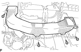
| 18. INSTALL HEATER TO REGISTER NO.4 DUCT |
- HINT:
- Use the same procedures for the heater to register No.4 duct and the heater to register No.1 duct.
| 19. INSTALL DEFROSTER NOZZLE ASSEMBLY |
Install the 3 screws <C> and the defroster nozzle assembly.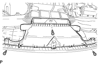
| 20. INSTALL INSTRUMENT PANEL NO.1 PIN |
Install the screw <C> and the instrument panel No.1 pin.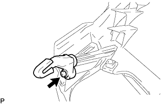
| 21. INSTALL SIDE DEFROSTER NO.3 NOZZLE DUCT |
Install the screw <C> and the side defroster No.3 nozzle duct.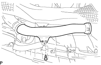
| 22. INSTALL SIDE DEFROSTER NO.4 NOZZLE DUCT |
- HINT:
- Use the same procedures for the side defroster No.4 nozzle duct and the side defroster No.3 nozzle duct.
| 23. INSTALL LIGHT CONTROL RHEOSTAT |
Engage the 2 claws and install the light control rheostat.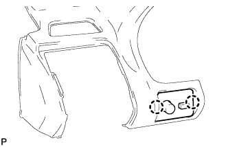
| 24. INSTALL FRONT NO.2 SPEAKER |
Connect the connector.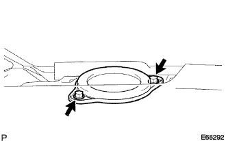
Install the front No.2 speaker.
| 25. INSTALL FRONT NO.2 SPEAKER |
Connect the connector.
Install the front No.2 speaker.
| 26. INSTALL FRONT NO.2 SPEAKER (w/ Mark Levinson Speaker System) |
Connect the connector.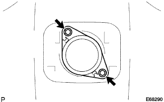
Install the front No.2 speaker with the 2 bolts.
| 27. INSTALL INSTRUMENT PANEL NO.1 SPEAKER PANEL SUB-ASSEMBLY |
Engage the 2 clips and install the instrument panel No.1 speaker panel sub-assembly.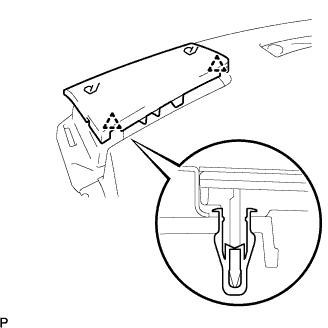
| 28. INSTALL INSTRUMENT PANEL NO.2 SPEAKER PANEL SUB-ASSEMBLY |
- HINT:
- Use the same procedures for the instrument panel No.2 speaker panel sub-assembly and the instrument panel No.1 speaker panel sub-assembly.
| 29. INSTALL SPEAKER NO.1 HOLE COVER (w/ Mark Levinson Speaker System) |
Engage the 4 clips and install the speaker hole No.1 cover.