Theft Warning Siren Circuit
Circuit diagnosis
DESCRIPTION
The theft warning siren has an internal battery. If any of the vehicle's battery or communication line is opened, the theft warning siren detects it by itself and sounds. Although the theft warning siren sounds by receiving a signal from the multiplex network body ECU usually, the theft warning siren can sound by its internal battery in case that the circuit of the vehicle's battery is opened.The multiplex network body ECU sends an arming signal to the theft warning siren while transferring to the Armed State, and it also sounds a disarming signal to the siren while switching to the Disarmed State. Besides, the multiplex network body ECU can cause the theft warning siren to sound by sending an alarm signal during the Alarm Sounding State.
WIRING DIAGRAM


INSPECTION PROCEDURE
| 1. PERFORM ACTIVE TEST BY INTELLIGENT TESTER |

Connect the intelligent tester to the DLC3.
Turn the ignition switch ON.
Turn the intelligent tester main switch on.
Select the item below in the ACTIVE TEST and then check that the horn operate.
BODY (Multiplex network body ECU): Item
Test Details
Diagnostic Note
Security Horn
Security horn (theft warning siren) ON/OFF
-
- OK:
- The theft warning siren sounds or stops correctly when operating it through the intelligent tester.
|
|
||||

| OK | ||
 |
||
| ||
| 2. INSPECT FUSE (FUEL OPN) |
Remove the FUEL OPN fuse from the instrument panel J/B.
Measure the resistance.
- Resistance:
- Below 1 Ω
|
|
||||

| OK | |
 |
| 3. CHECK HARNESS AND CONNECTOR (INSTRUMENT PANEL J/B ASSEMBLY - BATTERY) |
Install the FUEL OPN fuse to instrument panel J/B.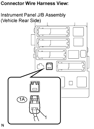
Disconnect the 1A connector.
Measure the voltage according to the value(s) in the table below.
- Voltage:
Tester Connection
Condition
Specified Condition
1A-1 - Body ground
Always
10 to 14 V
|
|
||||
| OK | |
|
| 4. CHECK HARNESS AND CONNECTOR (INSTRUMENT PANEL J/B ASSEMBLY - THEFT WARNING SIREN ASSEMBLY) |
Disconnect the 1J connector and T18 siren connector.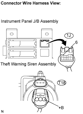
Measure the resistance according to the value(s) in the table below.
- Resistance:
Symbol (Tester Connection)
Specified Condition
1J-6 - +B (T18-1)
Below 1 Ω
1J-6 or +B (T18-1) - Body ground
10 kΩ or higher
|
|
||||
| OK | |
|
| 5. CHECK THEFT WARNING SIREN ASSEMBLY |
Reconnect 1A and 1J J/B connectors, and T18 siren connector.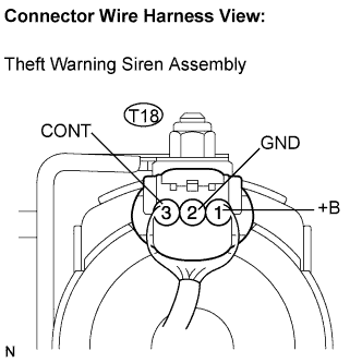
Measure the voltage according to the value(s) in the table below.
- Voltage:
Symbol (Tester Connection)
Condition
Specified Condition
+B (T18-1) - Body ground
Always
10 to 14 V
GND (T18-2) - Body ground
Always
Below 1 V
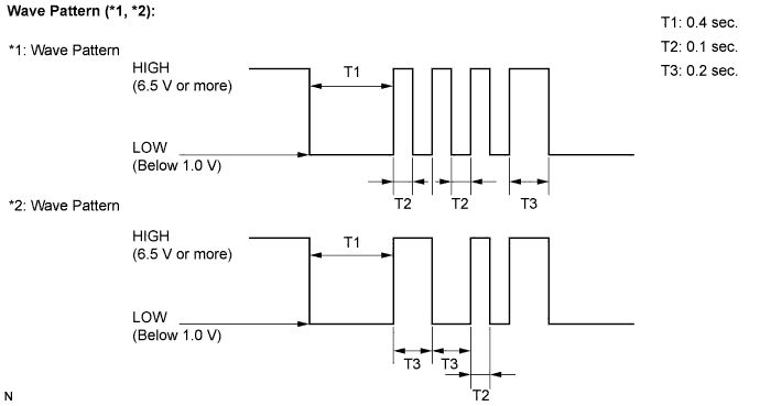
CONT (T18-3) - Body ground
When switched from armed state or arming preparation state to disarmed state (1)
Pulse generation*1
(Using an oscilloscope)
When switched from arming preparation state to armed state (2)
Pulse generation*2
(Using an oscilloscope)
Normal condition (Except (1) and (2))
Approx. 1.4 V
Wave pattern (*1, *2)
|
|
||||
| OK | |
|
| 6. CHECK HARNESS AND CONNECTOR (MULTIPLEX NETWORK BODY ECU - THEFT WARNING SIREN ASSEMBLY) |
Disconnect the B7 ECU connector and T18 siren connector.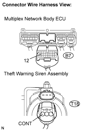
Measure the resistance according to the value(s) in the table below.
- Resistance:
Symbol (Tester Connection)
Specified Condition
SSCL (B7-12) - CONT (T18-3)
Below 1 Ω
|
|
||||
| OK | |
|
| 7. CHECK HARNESS AND CONNECTOR (THEFT WARNING SIREN ASSEMBLY - BODY GROUND) |
Disconnect T18 siren connector.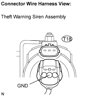
Measure the resistance according to the value(s) in the table below.
- Resistance:
Symbol (Tester Connection)
Specified Condition
GND (T18-2) - Body ground
Below 1 Ω
|
|
||||
| OK | ||
|
||
| ||