Intrusion Sensor Circuit
Circuit diagnosis
DESCRIPTION
The intrusion sensor (theft warning sensor) detects any moving object by using ultrasonic waves and outputs the signals to inform the multiplex network body ECU of intrusion, so that the theft deterrent system can set off the alarm.WIRING DIAGRAM
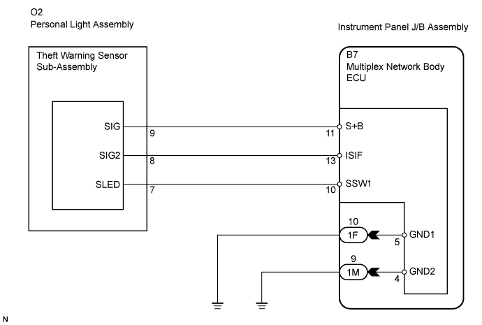

INSPECTION PROCEDURE
| 1. CHECK THEFT WARNING SENSOR SUB-ASSEMBLY (OPERATION) |

Set the theft deterrent system with a window open and after 20 seconds insert your hand through the window and shake it near the sensor to check if the alarm is triggered.
- OK:
- The alarm is triggered.
|
|
||||

| OK | |
 |
| 2. PERFORM ACTIVE TEST BY INTELLIGENT TESTER |
Connect the intelligent tester to the DLC3.
Turn the ignition switch ON.
Turn the intelligent tester main switch on.
Select the item below in the ACTIVE TEST and then check that the horns operate.
BODY (Multiplex network body ECU): Item
Test Details
Diagnostic Note
Intrusion Sensor Power
Intrusion sensor power ON/OFF
-
Result: Result
Go To
OFF
Sensor power is OFF position
ON
A
| A | |
|
| 3. CHECK THEFT WARNING SENSOR SUB-ASSEMBLY (PERSONAL LIGHT ASSEMBLY) |
Measure the voltage and resistance according to the value(s) in the table below.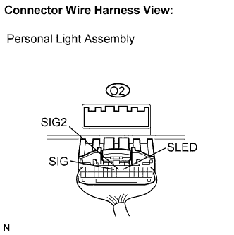
- Standard:
Symbol (Tester Connection)
Condition
Specified Condition
SIG (O2-9) - Body ground
Arming preparation state or armed state
10 to 14 V
Disarmed state
Below 1 V
SIG2 (O2-8) - Body ground
No moving object detected by sensor
10 to 14 V
Moving object detected by sensor during arming preparation state or armed state
Using an oscilloscope*
SLED (O2-7) - Body ground
OFF switch ON
Below 1 Ω
OFF switch OFF
10 kΩ or higher
Wave pattern (*)
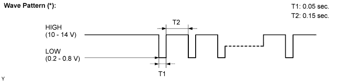
|
|
||||
| OK | |
|
| 4. CHECK HARNESS AND CONNECTOR (MULTIPLEX NETWORK BODY ECU - THEFT WARNING SENSOR ASSEMBLY) |
Disconnect the B7 ECU and O2 light connector.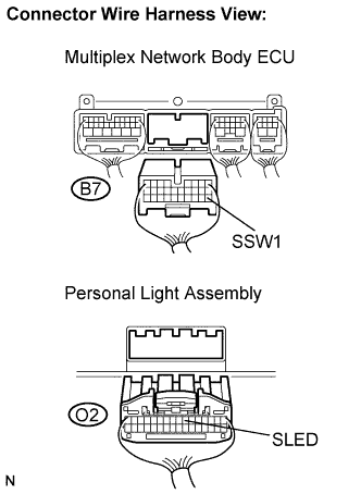
Measure the resistance according to the value(s) in the table below.
- Resistance:
Symbol (Tester Connection)
Specified Condition
SSW1 (B7-10) - SLED (O2-7)
Below 1 Ω
|
|
||||
| OK | ||
 |
||
| ||