Display Signal Circuit between Navigation ECU and Television Camera ECU
Circuit diagnosis
DESCRIPTION
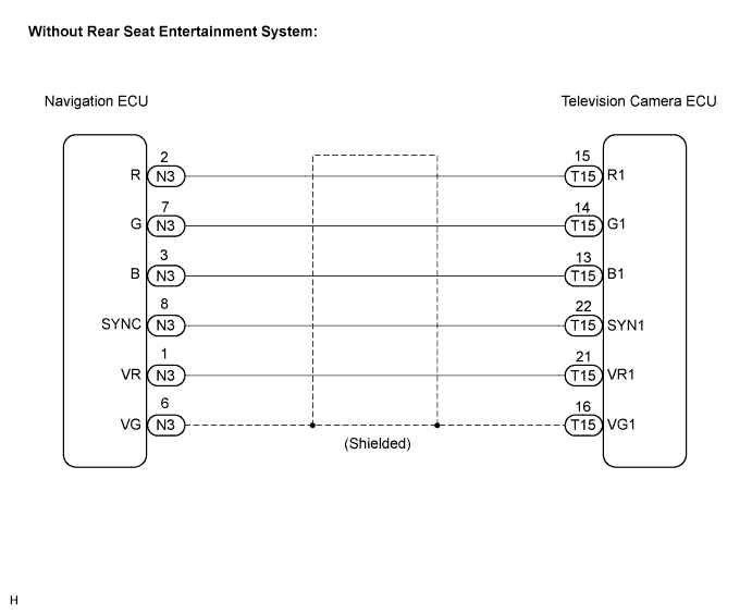
This is the display signal circuit from the navigation ECU to the television camera ECU.WIRING DIAGRAM

INSPECTION PROCEDURE
| 1. CHECK HARNESS AND CONNECTOR (NAVIGATION ECU - TELEVISION CAMERA ECU) |

Disconnect the navigation ECU connector N3 and television camera ECU connector T15.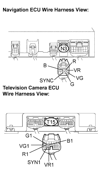
Measure the resistance according to the value(s) in the table below.
- Resistance:
Tester connection
Condition
Specified condition
R - R1
Always
Below 1 Ω
G - G1
Always
Below 1 Ω
B - B1
Always
Below 1 Ω
SYNC - SYN1
Always
Below 1 Ω
VR - VR1
Always
Below 1 Ω
VG - VG1
Always
Below 1 Ω
R - Body ground
Always
10 kΩ or higher
G - Body ground
Always
10 kΩ or higher
B - Body ground
Always
10 kΩ or higher
SYNC - Body ground
Always
10 kΩ or higher
VR - Body ground
Always
10 kΩ or higher
|
|
||||

| OK | |
 |
| 2. INSPECT NAVIGATION ECU (OUTPUT SIGNAL) |
Reconnect the navigation ECU connector N3.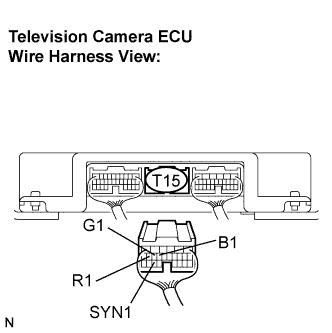
Measure the waveform according to the table below.
- OK:
Tester connection
Condition
Specified condition
R1 - Body ground
Navigation map is switched
A waveform synchronized with display signals is output
G1 - Body ground
Navigation map is switched
A waveform synchronized with display signals is output
B1 - Body ground
Navigation map is switched
A waveform synchronized with display signals is output
SYN1 - Body ground
Navigation display is ON
A waveform synchronized with display signals is output
- HINT:
- The waveform pattern may differ from those shown in the illustrations below due to differences in oscilloscope setting. A normal navigation ECU operating condition can be determined if any waveform is output.
Oscilloscope wave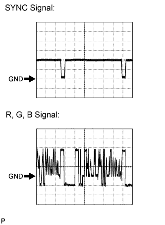
Terminal: SYNC - Body groundSetting: 500 mV/DIV 10 μs/DIVCondition: Navigation display is ON.
Terminal: R, G, B - Body groundSetting: 200 mV/DIV 10 μs/DIVCondition: Navigation map is switched.
|
|
||||
| OK | ||
 |
||
| ||