Display Signal Circuit between Television Camera ECU and Multi-display
Circuit diagnosis
DESCRIPTION
This is the display signal circuit from the television camera ECU to the multi-display.WIRING DIAGRAM
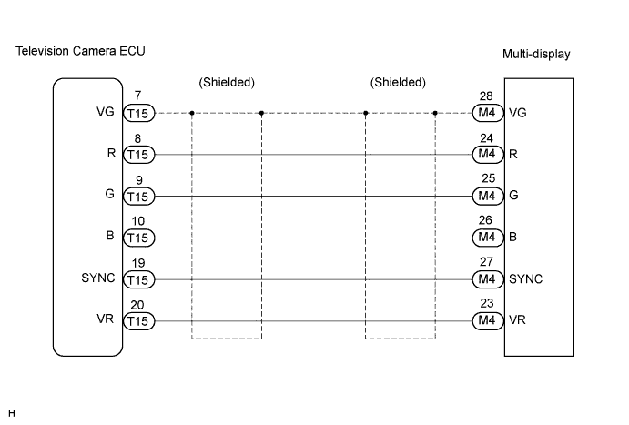

INSPECTION PROCEDURE
| 1. CHECK HARNESS AND CONNECTOR (TELEVISION CAMERA ECU - MULTI-DISPLAY) |

Disconnect the television camera ECU connector T15 and multi-display connector M4.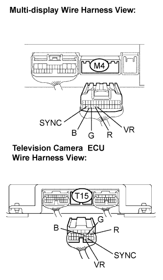
Measure the resistance according to the value(s) in the table below.
- Resistance:
Tester connection
Condition
Specified condition
R - R
Always
Below 1 Ω
G - G
Always
Below 1 Ω
B - B
Always
Below 1 Ω
SYNC - SYNC
Always
Below 1 Ω
VR - VR
Always
Below 1 Ω
R - Body ground
Always
10 kΩ or higher
G - Body ground
Always
10 kΩ or higher
B - Body ground
Always
10 kΩ or higher
SYNC - Body ground
Always
10 kΩ or higher
VR - Body ground
Always
10 kΩ or higher
|
|
||||

| OK | |
 |
| 2. INSPECT TELEVISION CAMERA ECU (OUTPUT SIGNAL) |
Reconnect the television camera ECU connector T15.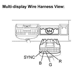
Measure the waveform according to the table below.
- OK:
Tester connection
Condition
Specified condition
R - Body ground
Navigation map is switched
A waveform synchronized with display signals is output
G - Body ground
Navigation map is switched
A waveform synchronized with display signals is output
B - Body ground
Navigation map is switched
A waveform synchronized with display signals is output
SYNC - Body ground
Navigation display is ON
A waveform synchronized with display signals is output
- HINT:
- The waveform pattern may differ from those shown in the illustrations below due to differences in oscilloscope setting. A normal television camera ECU operating condition can be determined if any waveform is output.
Oscilloscope wave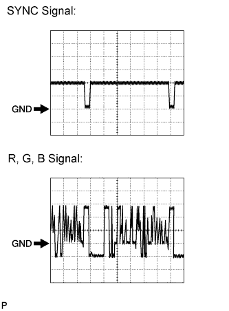
Terminal: SYNC - Body groundSetting: 500 mV/DIV 10 μs/DIVCondition: Navigation display is ON.
Terminal: R, G, B - Body groundSetting: 200 mV/DIV 10 μs/DIVCondition: Navigation map is switched.
|
|
||||
| OK | ||
 |
||
| ||