P2601-777
Diagnostic trouble codes
DESCRIPTION
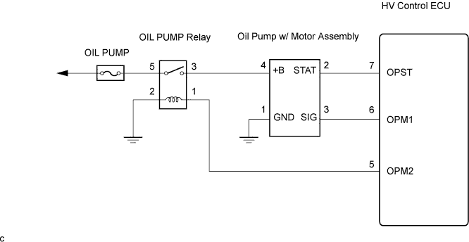
The HV control ECU detects the Generator and Motor temperature through signals from the generator and motor temperature sensors and activates the oil pump relay and oil pump driver (oil pump w/ motor assembly).The HV control ECU monitors OPST signals from the oil pump driver and detects a malfunction.
| DTC No. |
INF No. |
DTC Detection Condition |
Trouble Area |
| P2601 |
777 |
Command signal (OPM1) from HV control ECU is abnormal |
|
The oil pump w/ motor assembly is activated when:
1. Generator temperature is 120°C (248°F) or more
2. Motor temperature is 130°C (266°F) or more and Generator temperature is 100°C (212°F) or more
- HINT:
- In case of the second condition, if the oil pump w/ motor assembly is not activated even though the Generator temperature is 10 °C (212°F) or more, attempt to activate the oil pump w/ motor assembly by changing the Generator temperature to 110 (200), 120 (248), 130 (266), 140 (284) and 150°C (302°F) respectively.
- The oil pump cannot be activated only with the oil pump relay on. It is activated after receiving the command signals (OPM1) from the HV control ECU.
- In case of the second condition, if the oil pump w/ motor assembly is not activated even though the Generator temperature is 10 °C (212°F) or more, attempt to activate the oil pump w/ motor assembly by changing the Generator temperature to 110 (200), 120 (248), 130 (266), 140 (284) and 150°C (302°F) respectively.
WIRING DIAGRAM

INSPECTION PROCEDURE
- NOTICE:
- When troubleshooting the oil pump w/ motor assembly, check for the following conditions:
- ATF temperature inside the oil cooler is 5°C (41°F) or more.
- Value of the ambient temperature sensor is 5°C (41°F) or more.
- When troubleshooting the oil pump w/ motor assembly, check for the following conditions:
| 1. CHECK OPERATION OIL PUMP W/MOTOR ASSEMBLY |

Connect the intelligent tester to the DLC3.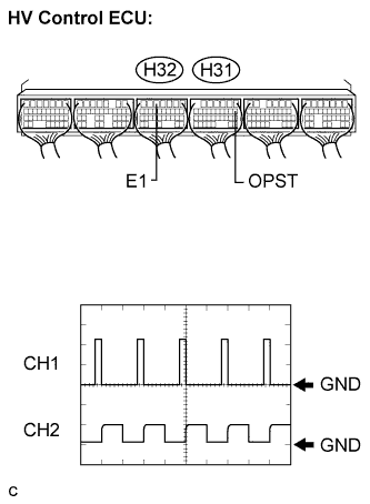
Turn the ignition switch to the ON position.
Select the following menu items: Powertrain / Hybrid Control /Active Test / Inspection Mode.
Check the waveform between the terminals of the HV control ECU.
- OK:
Tester Connection
Specified Condition
OPM1 (H31-6)- E1 (H32-5)
The waveform appears as shown in the illustration.
- Result:
Waveform
Proceed to
Normal waveform
A
Waveform other than normal waveform
B
No waveform (0 V)
C
No waveform (12 V)
D
|
|
||||
|
|
||||
|
|
||||


| A | ||
 |
||
| ||
| 2. CHECK HARNESS AND CONNECTOR (HV CONTROL ECU - OIL PUMP W/MOTOR ASSEMBLY) |
Disconnect O3 oil pump w/ motor assembly connector.
Disconnect the H31 connector from the HV control ECU.
Measure the resistance according to the value(s) in the table below.
- Standard Resistance (Check for open):
Tester Connection
Specified Condition
OPM1 (H31-6) - SIG (O3-3)
Below 1 Ω
- Standard Resistance (Check for short):
Tester Connection
Specified Condition
OPM1 (H31-6) or SIG (O3-3) - Body ground
10 kΩ or higher
Reconnect the HV control ECU connector.
|
|
||||
| OK | |
 |
| 3. INSPECT HV CONTROL ECU (OPM1 TERMINAL CONTINUITY CHECK) |
Disconnect the H32 and H31 HV control ECU connectors.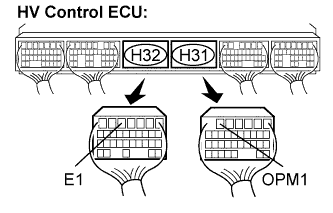
Check the continuity between each terminal.
- Standard Resistance:
Tester Connection
Specified Condition
OPM1 (H31-6) - E1 (H32-5)
10 kΩ or higher
|
|
||||
| OK | ||
|
||
| ||
| 4. CHECK HARNESS AND CONNECTOR (HV CONTROL ECU - OIL PUMP W/MOTOR ASSEMBLY) |
Disconnect the O3 oil pump w/ motor assembly connector.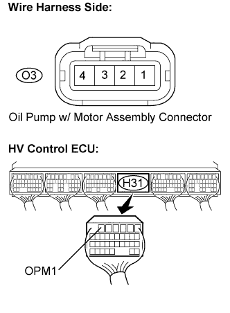
Disconnect the H31 HV control ECU connector.
Measure the voltage according to the value(s) in the table below when the ignition switch is in the ON position.
- Standard Voltage:
Tester Connection
Specified Condition
OPM1 (H31-6) - Body ground
Below 1 V
|
|
||||
| OK | |
|
| 5. INSPECT OIL PUMP W/MOTOR ASSEMBLY |
Measure the resistance according to the value(s) in the table below.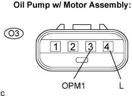
- Standard Resistance:
Tester Connection
Specified Condition
+B (O3-4) - SIG (O3-3)
10 kΩ or higher
|
|
||||
| OK | ||
|
||
| ||