P2603-768
Diagnostic trouble codes
DESCRIPTION
Refer to the description for DTC P2601-777. (Click here)| DTC No. |
INF No. |
DTC Detection Condition |
Trouble Area |
| P2603 |
768 |
|
|
WIRING DIAGRAM
Refer to the wiring diagram for DTC P2601-777. (Click here)INSPECTION PROCEDURE
- NOTICE:
- When troubleshooting the oil pump w/ motor assembly, check for the following conditions.
- ATF temperature inside the oil cooler is 5°C (41 °F) or more.
- Value of the ambient temperature sensor is 5°C (41 °F) or more.
- When troubleshooting the oil pump w/ motor assembly, check for the following conditions.
| 1. INSPECT OIL PUMP FUSE |

Remove the oil pump fuse from the engine room R/B No.4.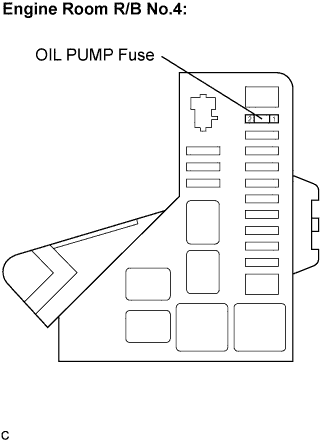

Check continuity of the oil pump fuse.
- OK:
- There is continuity.
|
|
||||

| OK | |
 |
| 2. INSPECT OIL PUMP RELAY |
Remove the oil pump relay from the engine room R/B No.4.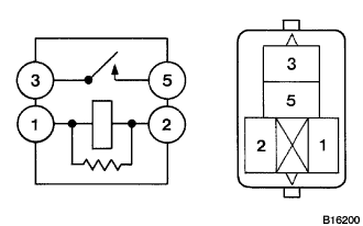
Measure the resistance according to the value(s) in the table below.
- Standard Resistance:
Tester Connection
Specified Condition
1 - 2
Below 1 Ω
3 - 5
10 kΩ or higher
Below 1 Ω
(Apply battery voltage between terminals 1 and 2)
|
|
||||
| OK | |
|
| 3. CHECK HARNESS AND CONNECTOR (HV CONTROL ECU - OIL PUMP RELAY, OIL PUMP RELAY - OIL PUMP) |
Remove the oil pump relay from the engine room R/B No.4.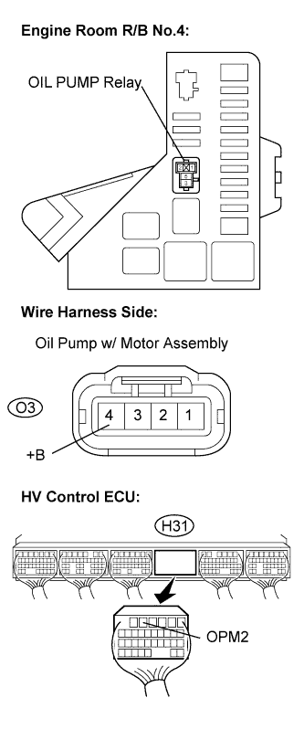
Disconnect the O3 oil pump w/ motor assembly connector.
Disconnect the H31 HV control ECU connector.
Measure the resistance according to the value(s) in the table below.
- Standard Resistance (Check for open):
Tester Connection
Specified Condition
OPM2 (H31-5) - Engine room R/B No.4 OIL PUMP relay terminal 1
Below 1 Ω
- Standard Resistance (Check for short):
Tester Connection
Specified Condition
OPM2 (H31-5) or Engine room R/B No.4 OIL PUMP relay terminal 1 - Body ground
10 kΩ or higher
Measure the resistance according to the value(s) in the table below.
- Standard Resistance (Check for open):
Tester Connection
Specified Condition
Engine room R/B No.4 OIL PUMP relay terminal 2 - +B (O3-1)
Below 1 Ω
- Standard Resistance (Check for short):
Tester Connection
Specified Condition
Engine room R/B No.4 OIL PUMP relay terminal 2 or +B (O3-1) - Body ground
10 kΩ or higher
|
|
||||
| OK | |
|
| 4. CHECK HARNESS AND CONNECTOR (HV CONTROL ECU - OIL PUMP) |
Disconnect the O3 oil pump w/ motor assembly connector.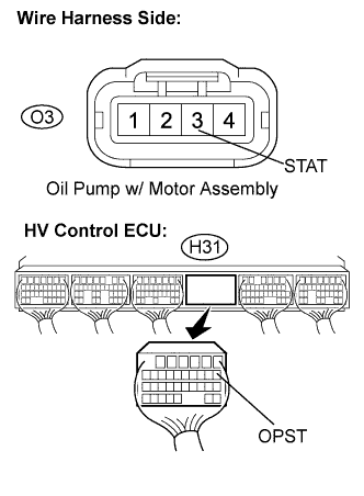
Disconnect the H31 HV control ECU connector.
Measure the voltage according to the value(s) in the table below when the ignition switch is in the ON position.
- Standard Voltage:
Tester Connection
Specified Value
OPST (H31-7) or STAT (O3-2) - Body ground
Below 1 V
Turn the ignition switch off.
Measure the resistance according to the value(s) in the table below.
- Standard Resistance:
Tester Connection
Specified Condition
OPST (H31-7) - STAT (O3-2)
Below 1 Ω
|
|
||||
| OK | |
|
| 5. INSPECT HYBRID VEHICLE CONTROL ECU |
Remove the oil pump relay from the engine room R/B No.4.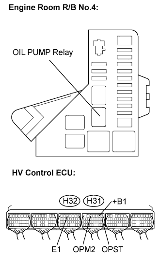
Connect the intelligent tester to the DLC3.
Turn the ignition switch to the ON position.
Select the following menu items: Powertrain / Hybrid Control /Active Test / Inspection Mode.
Put the vehicle into the READY-on state.
Measure the voltage according to the value(s) in the table below.
- Standard Voltage:
Tester Connection
Specified Value
OPM2 (H31-5) - E1 (H32-5)
10 to 14 V
Turn the ignition switch off.
Measure the resistance according to the value(s) in the table below.
- Standard Resistance:
Tester Connection
Specified Condition
OPST (H31-7) - +B1 (H31-2)
10 kΩ or higher
|
|
||||
| OK | ||
 |
||
| ||