INSTALLATION
Removal / installation
| 1. INSTALL EARTH WIRE |

Install the earth wire to the DC-DC converter assembly with the nut.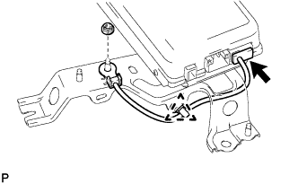

- Torque:
- 5.5 N*m{ 56 kgf*cm , 49 in.*lbf }
Connect the earth wire clamp to the DC-DC converter assembly.
Connect the earth wire connector to the DC-DC converter assembly.
| 2. INSTALL DC-DC CONVERTER ASSEMBLY |
- CAUTION:
- Be sure to wear insulated gloves.
Install the DC-DC converter assembly with the 4 nuts.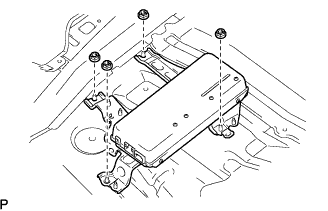
- Torque:
- 5.0 N*m{ 51 kgf*cm , 44 in.*lbf }
Connect the 3 connectors to the DC-DC converter assembly.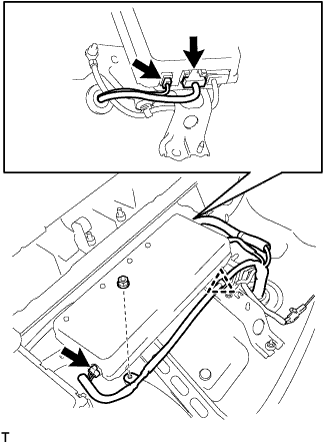
Connect the wire harness clamp to the DC-DC converter assembly.
Install the nut.
- Torque:
- 5.5 N*m{ 56 kgf*cm , 49 in.*lbf }
| 3. CHECK HIGH VOLTAGE CABLE CONNECTION |
- CAUTION:
- Be sure to wear insulated gloves.
Check that the high voltage cable connector is securely connected to the DC-DC converter assembly.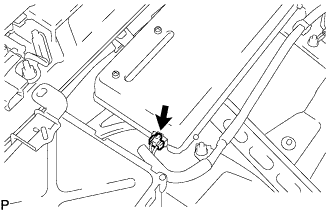
| 4. INSTALL POWER STEERING CONVERTER COVER |
Install the power steering converter cover with the 3 nuts.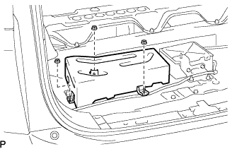
- Torque:
- 5.0 N*m{ 51 kgf*cm , 44 in.*lbf }
Install the wire harness clamp to the power steering converter cover.
| 5. INSTALL DECK BOARD CHECK NO.1 |
Install the deck board check No.1 with the 4 nuts.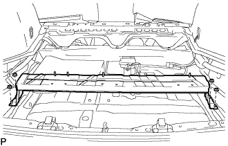
| 6. INSTALL DECK SIDE TRIM BOX LH |
Install the deck side trim box with the 2 clips.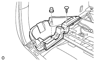
| 7. INSTALL DECK SIDE TRIM BOX RH |
- HINT:
- Perform the same procedure as for the LH side.
| 8. INSTALL JACK CARRIER ASSEMBLY |
| 9. INSTALL JACK ASSEMBLY |
| 10. INSTALL JACK CARRIER SUPPORT |
| 11. INSTALL DECK BOARD SUB-ASSEMBLY NO.3 |
Install the deck No.3 board sub-assembly with the 2 bolts and 2 nuts.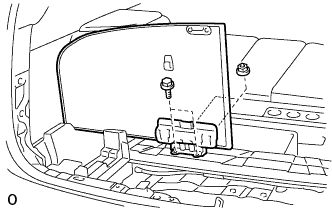
| 12. INSTALL DECK BOARD SUB-ASSEMBLY NO.2 |
Install the deck No.2 board sub-assembly with the 4 bolts and 2 nuts.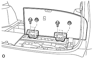
| 13. INSTALL DECK FLOOR BOX FRONT |
Install the deck floor box front with the 2 clips.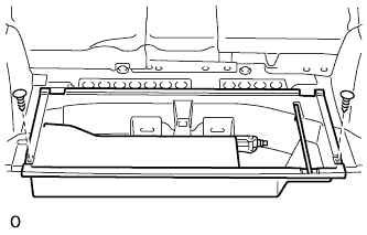
| 14. INSTALL REAR FLOOR FINISH PLATE |
Engage the 2 claws and 6 clips, and install the rear floor finish plate.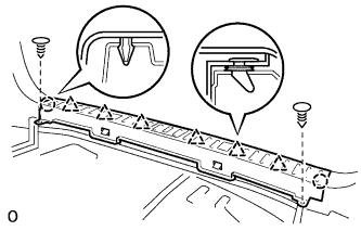
Install the 2 clips.
| 15. INSTALL DECK FLOOR BOX REAR |
Install the deck floor box rear with the 2 clips.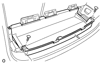
| 16. INSTALL DECK BOARD SUB-ASSEMBLY |
Install the deck board sub-assembly with the 2 bolt.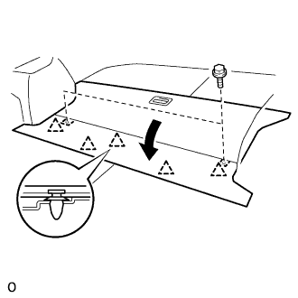
Engage the 5 clips.
| 17. INSTALL SERVICE PLUG GRIP |
- NOTICE:
- Before connecting the service plug, check that no parts and tools remain and that the high voltage terminals and connectors are connected securely.
Wear insulation gloves, then insert the service plug.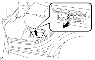
Push down on the grip to lock.
Close the battery service hole cover.
- NOTICE:
- Check that the 2 battery service hole cover clips are securely connected to the battery carrier bracket (click sound).
| 18. CONNECT CABLE TO NEGATIVE BATTERY TERMINAL |
| 19. PERFORM INITIALIZATION |
Some systems need initialization when disconnecting the cable from the negative battery terminal (Click here).