01-D6
Diagnostic trouble codes
DESCRIPTION
| DTC No. |
DTC Detection Condition |
Trouble Areas |
| 01-D6 *1 |
When either of the following conditions is met:
|
|
| 01-D7 *2 |
When either of the following conditions is met:
|
- HINT:
- *1: Even if no failure is detected, a trouble code may be recorded depending on the battery condition or engine start voltage.
- *2: When 210 seconds have elapsed after disconnecting the power supply connector of the master component with the ignition switch in the ACC or ON position, this code is stored.
- *1: Even if no failure is detected, a trouble code may be recorded depending on the battery condition or engine start voltage.
- NOTICE:
- Be sure to clear and recheck DTCs and perform inspection according to the result to avoid the conditions shown in the "HINT" above.
- The radio receiver is the master unit.
- Be sure to clear and recheck DTCs after the inspection is completed to confirm that no DTCs are output.
- Be sure to clear and recheck DTCs and perform inspection according to the result to avoid the conditions shown in the "HINT" above.
INSPECTION PROCEDURE
- NOTICE:
- Be sure to read DESCRIPTION before performing the following procedures.
| 1. CHECK RADIO RECEIVER POWER SOURCE CIRCUIT |

If the power source circuit is operating normally, proceed to the next step.
| NEXT | |
 |
| 2. IDENTIFY THE COMPONENT WHICH HAS STORED THIS CODE |
Enter the diagnostic mode.
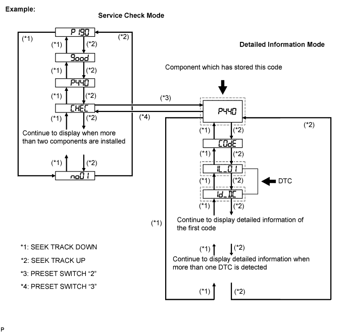

Press the preset switch "3" to change to "Detailed Information Mode".
Identify the component which has stored this code.
Component Table Component
Physical address
Gateway ECU
1C6
Stereo Component Amplifier
440
- HINT:
- The "440 (stereo component amplifier)" is the component which has stored this code in the example shown in the illustration.
- For details of the DTC display, refer to the "DTC CHECK/CLEAR" (Click here).
- The "440 (stereo component amplifier)" is the component which has stored this code in the example shown in the illustration.
| NEXT | |
|
| 3. CHECK POWER SOURCE CIRCUIT OF THE COMPONENT THAT DTC IS OUTPUT |
Inspect the power source circuit of the component which has stored this code.If the power source circuit is operating normally, proceed to the next step.
Component Table Component
Proceed to
Gateway ECU
Gateway ECU power source circuit (Click here)
Stereo Component Amplifier
Stereo component amplifier power source circuit (Click here)
| NEXT | |
|
| 4. INSPECT RADIO RECEIVER |
Disconnect the radio receiver connectors.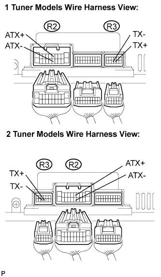
Measure the resistance according to the value(s) in the table below.
- Resistance:
Tester Connection
Condition
Specified Condition
ATX+ (R2-5) - ATX- (R2-15)
Always
60 to 80 Ω
TX+ (R3-9) - TX- (R3-10)
Always
60 to 80 Ω
|
|
||||

| OK | |
|
| 5. CHECK HARNESS AND CONNECTOR (RADIO RECEIVER - COMPONENT WHICH HAS STORED THIS CODE) |
- HINT:
- For details of the connectors, refer to the "Terminals of ECU" (Click here).
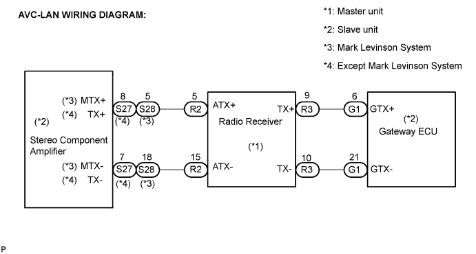
Referring to the AVC-LAN wiring diagram below, check the AVC-LAN circuit between the radio receiver and the component which has stored this code.
Check for open or short in the AVC-LAN circuit between the radio receiver and the component which has stored this code.
- OK:
- There is no open or short circuit.
|
|
||||
| OK | |
|
| 6. REPLACE COMPONENT WHICH HAS STORED THIS CODE |
Replace the component which has stored this code with a normal one and check if the same problem occurs again.
- OK:
- Same problem does not occur.
|
|
||||
| OK | ||
 |
||
| ||