5C-40
Diagnostic trouble codes
DESCRIPTION
| DTC |
DTC Detection Condition |
Trouble Area |
| 5C-40 |
Synchronous signal from the camera cannot be transmitted |
Television camera ECU Television camera assembly Wire harness |
WIRING DIAGRAM
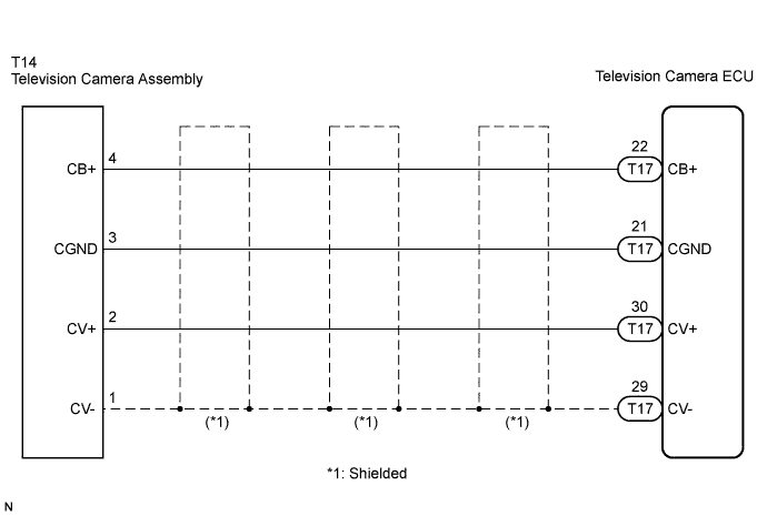

INSPECTION PROCEDURE
| 1. CHECK NAVIGATION DISPLAY |

Check whether navigation display appears properly or not.
- OK:
- The navigation display properly appears.
- HINT:
- When the navigation display has trouble, inspect the circuit between the television camera ECU and multi-display assembly (Click here).
- When the navigation display is normal, inspect the circuit between the television camera ECU and television camera assembly by following the steps below.
- When the navigation display has trouble, inspect the circuit between the television camera ECU and multi-display assembly (Click here).
|
|
||||

| OK | |
 |
| 2. CHECK HARNESS AND CONNECTOR (TELEVISION CAMERA ECU AND TELEVISION CAMERA ASSEMBLY) |
Disconnect the T17 connector from the television camera ECU.
Disconnect the T14 connector from the television camera assembly.
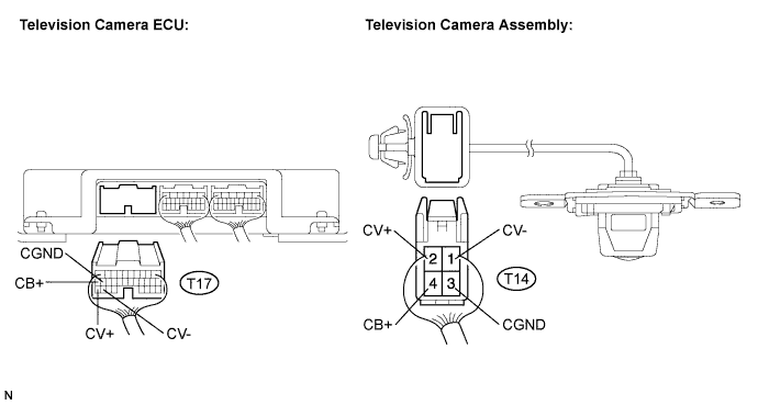
Measure the resistance according to the value(s) in the table below.
- Standard resistance:
Tester connection
(Terminal No.)
Condition
Specified condition
CB+ (T17-22) - CB+ (T14-4)
Always
Below 1 Ω
CGND (T17-21) - CGND (T14-3)
Always
Below 1 Ω
CV+ (T17-30) - CV+ (T14-2)
Always
Below 1 Ω
CV- (T17-29) - CV- (T14-1)
Always
Below 1 Ω
CB+ (T17-22) - Body ground
Always
10 kΩ or higher
CGND (T17-21) - Body ground
Always
10 kΩ or higher
CV+ (T17-30) - Body ground
Always
10 kΩ or higher
CV- (T17-29) - Body ground
Always
10 kΩ or higher
|
|
||||
| OK | |
|
| 3. INSPECT TELEVISION CAMERA ECU |
Connect the T17 connector to the television camera ECU.
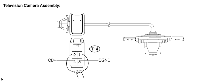
Measure the voltage according to the value(s) in the table below.
- Standard voltage:
Tester connection
(Terminal No.)
Condition
Specified condition
CB+ (T14-4) - CGND (T14-3)
IG SW ON, shift lever R position
Approx. 6 V
|
|
||||
| OK | ||
 |
||
| ||