P2122-104
Diagnostic trouble codes
DESCRIPTION
Refer to the description for DTC P2120-111. (Click here)| DTCNo. |
INF Code |
DTC Detection Condition |
Trouble Area |
| P2122 |
104 |
Open or GND short in main sensor circuit |
|
| P2123 |
105 |
+B short in main sensor circuit |
|
| P2127 |
107 |
Open or GND short in sub sensor circuit |
|
| P2128 |
108 |
+B short in sub sensor circuit |
|
WIRING DIAGRAM
Refer to the wiring diagram for DTC P2120-111. (Click here)INSPECTION PROCEDURE
| 1. READ VALUE OF INTELLIGENT TESTER (ACCEL POS #1 AND #2) |

Connect the intelligent tester to the DLC3.
Turn the ignition switch to the ON position.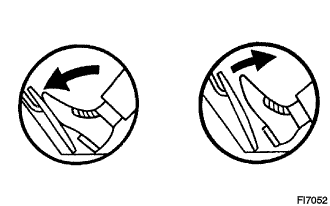

Select the following menu items: Powertrain / Hybrid Control / Data List / Accel Pos #1 and #2.
Read the voltage for the accelerator pedal position sensor data.
- Result:
Accelerator Pedal
Accel Pos #1
Accel Pos #2
Released
0.4 to 1.4 V
1.0 to 2.2 V
Depressed
3.1 to 4.6 V
3.9 to 5.0 V
|
|
||||

| NG | |
 |
| 2. INSPECT HYBRID VEHICLE CONTROL ECU |
Disconnect the A15 accelerator pedal position sensor connector.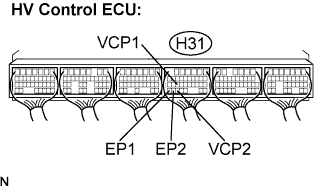
Turn the ignition switch to the ON position.
Measure the voltage according to the value(s) in the table below.
- Standard Voltage:
Tester Connection
Specified Condition
VCP1 (H31-24) - EP1 (H31-33)
4.5 to 5.5 V
VCP2 (H31-31) - EP2 (H31-32)
4.5 to 5.5 V
|
|
||||
| OK | |
|
| 3. INSPECT HYBRID VEHICLE CONTROL ECU |
Connect the accelerator pedal position sensor connector.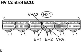
Turn the ignition switch to the ON position.
Measure the voltage according to the value(s) in the table below.
- Standard Voltage:
Pedal Position
VPA (H31-25) - EP1 (H31-33)
VPA2 (H31-26) - EP2 (H31-32)
Released
0.4 to 1.4 V
1.0 to 2.2 V
Depressed
3.1 to 4.6 V
3.9 to 5.0 V
|
|
||||
| NG | |
|
| 4. CHECK HARNESS AND CONNECTOR (HV CONTROL ECU - ACCELERATOR PEDAL POSITION SENSOR) |
Turn the ignition switch OFF.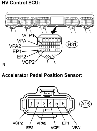
Disconnect the H31 HV control ECU connector.
Disconnect the A15 accelerator pedal position sensor connector.
Measure the voltage according to the value(s) in the table below.
- Standard Voltage:
Tester Connection
Specified Condition
VPA (H31-25) - Body ground
Below 1 V
VCP1 (H31-24) - Body ground
Below 1 V
EP1 (H31-33) - Body ground
Below 1 V
VPA2 (H31-26) - Body ground
Below 1 V
VCP2 (H31-31) - Body ground
Below 1 V
EP2 (H31-32) - Body ground
Below 1 V
Turn the ignition switch OFF.
Measure the resistance according to the value(s) in the table.
- Standard Resistance (Check for open):
Tester Connection
Specified Condition
VPA (H31-25) - VPA1 (A15-6)
Below 1 Ω
VCP1 (H31-24) - VCP1 (A15-4)
Below 1 Ω
EP1 (H31-33) - EP1 (A15-5)
Below 1 Ω
VPA2 (H31-26) - VPA2 (A15-1)
Below 1 Ω
VCP2 (H31-31) - VCP2 (A15-1)
Below 1 Ω
EP2 (H31-32) - EP2 (A15-2)
Below 1 Ω
- Standard Resistance (Check for short):
Tester Connection
Specified Condition
VPA (H31-25) or VPA1 (A15-6) - Body ground
10 kΩ or higher
VCP1 (H31-24) or VCP1 (A15-4) - Body ground
10 kΩ or higher
EP1 (H31-33) or EP1 (A15-5) - Body ground
10 kΩ or higher
VPA2 (H31-26) or VPA2 (A15-1) - Body ground
10 kΩ or higher
VCP2 (H31-31) or VCP2 (A15-1) - Body ground
10 kΩ or higher
EP2 (H31-32) or EP2 (A15-2) - Body ground
10 kΩ or higher
|
|
||||
| OK | ||
 |
||
| ||