Previous Next

Halfshaft

REMOVAL AND INSTALLATION

1993–94 323, 929, Miata and 1993–95 MX3 and 1993–97 Protege, 626, MX6
  1. Raise and safely support the vehicle. Remove the wheel and tire assemblies.
  2. Remove the splash shield, and drain the transaxle.
  3. Raise the staked portion of the hub locknut with a hammer and chisel. Lock the hub by applying the brakes and remove the nut.
  4. Disconnect the stabilizer bar and control link from the lower control arm.
  5. Remove the cotter pin and nut from the tie rod end ball stud. Use a suitable tool to separate the tie rod end from the knuckle.
  6. Remove the transverse member.
  7. Remove the lower ball joint pinch bolt and nut. Use a prybar to pry down the lower control arm and separate the ball joint from the knuckle.
  8. If removing the left side shaft with automatic transaxle:
    1. Suspend the engine using engine support tool 49 G017 5A0 or equivalent.
    2. Remove the bolts and nuts and remove the engine mount member.
  9. Position a prybar between the inner CV-joint and transaxle case. Carefully pry the halfshaft from the transaxle, being careful not damage the oil seal. If equipped with a right side intermediate shaft, insert the prybar between the halfshaft and intermediate shaft and tap on the bar to uncouple them.
  10. Pull outward on the hub/knuckle assembly, push the outer CV-joint stub shaft through the hub, and remove the halfshaft. If the halfshaft is stuck in the hub, install the old hub nut to protect the stub shaft threads. Tap on the nut, with only a soft mallet, and remove the halfshaft.

    NOTE: Install plug tool 49 G030 455 or equivalent, into the transaxle after removing the halfshaft, to keep the differential side gear in position. If the gear becomes mispositioned, the differential may have to be removed to realign the gear.

  11. If necessary, remove the intermediate shaft by removing the support bearing bolts and pulling the shaft from the transaxle.

    To install:

  12. If removed, install a new circlip on the end of the intermediate shaft, with the end gap facing upward.
  13. Install the intermediate shaft in the transaxle, being careful not to damage the oil seals. Install the support bearing bolts and tighten, in sequence, to 45 ft. lbs. (61 Nm).
  14. Install a new circlip on the end of the halfshaft, with the end gap facing upward. Insert the halfshaft into the transaxle, being careful not to damage the oil seal. If equipped, push the halfshaft into the intermediate shaft.
  15. Insert the other end of the halfshaft through the hub. Loosely install a new locknut.
  16. If installing the left side shaft with automatic transaxle, proceed as follows:
    1. Install the engine mount member. Tighten the mount member-to-body nuts and bolts to 66 ft. lbs. (89 Nm).
    2. Tighten the front mount-to-mount member nuts to 77 ft. lbs. (104 Nm) and the side mount bolts to 44 ft. lbs. (60 Nm).
    3. Remove the engine support tool.
  17. Install the lower ball joint into the knuckle. Install the pinch bolt and nut and tighten to 26–41 ft. lbs. (35–56 Nm).
  18. Install the transverse member, and tighten the bolts to 69–96.9 ft. lbs. (94–132 Nm).
  19. Connect the tie rod end to the steering knuckle and tighten the nut to 24–32 ft. lbs. (32–44 Nm). Install a new cotter pin. Tighten the nut, if necessary, to align the ball stud hole with the nut castellation.
  20. Connect the stabilizer bar to the lower control arm.
  21. Install the splash shield and the wheel and tire assemblies. Lower the vehicle.
  22. Lock the hub with the brakes. Tighten the new hub nut to 173.6–235 ft. lbs. (236–318 Nm). After torquing, stake the locknut using a hammer and dull bladed chisel.
  23. Fill the transaxle with the proper type and quantity of fluid.
RX7
  1. Raise and safely support the vehicle. Remove the wheel and tire assembly.
  2. Unstake and remove the wheel hub nut.
  3. On all except 1993–94 RX7, mark the position of the halfshaft on the output flange and remove the nuts.
  4. On Miata, remove the upper control arm bolt. On 1993–94 RX7, remove the lower control arm bolt.
  5. Remove the halfshaft.

    NOTE: If the halfshaft is stuck in the hub, install the used hub nut until it is flush with the end of the shaft. Tap on the nut, using only a soft mallet, to remove the halfshaft

    To install:

  6. On 1993–94 RX7, install a new circlip on the inner CV-joint, with the end gap facing upward.
  7. Install the halfshaft. On 1993 RX7, be careful not to damage the oil seal. On all except 1993–94 RX7, align the halfshaft on the output shaft flange and install the halfshaft-to-output flange nuts. Tighten the nuts to 47 ft. lbs. (64 Nm).
  8. On Miata, install the upper control arm bolt and tighten to 49 ft. lbs. (69 Nm). On 1993–94 RX7, install the lower control arm bolt and tighten to 54 ft. lbs. (73 Nm).
  9. Install the wheel and tire assembly and lower the vehicle.
  10. Install a new hub nut and tighten to 231 ft. lbs. (314 Nm) on all except Miata, where the torque is 217 ft. lbs. (294 Nm). Stake the hub nut, using a hammer and dull-bladed chisel.
1993–95 929
  1. Raise and safely support the vehicle. Remove the wheel and tire assemblies.
  2. Remove the exhaust pipe.
  3. Remove the rear lower lateral link.
  4. Matchmark and remove the driveshaft.
  5. Remove the upper and lower lateral links.
  6. Remove the stabilizer control link.
  7. Raise the staked portion of the hub locknut with a hammer and chisel. Lock the hub by applying the brakes and remove the nut.
  8. Matchmark the halfshaft and output shaft for proper alignment before removing the halfshaft.
  9. Support the subframe and differential with a jack. Remove the subframe mounting nuts and washers and lower the subframe and differential approximately 4 inches (100mm).
  10. Pull outward on the hub/knuckle assembly, push the outer CV-joint stub shaft through the hub, and remove the halfshaft. If the halfshaft is stuck in the hub, install the old hub nut to protect the stub shaft threads. Tap on the nut, with only a soft mallet, and remove the halfshaft.

    To install:

  11. Position the halfshaft with the matchmarks aligned, and install the mounting bolts. Torque the bolts to 40–47 ft. lbs. (54–63 Nm).
  12. Insert the other end of the halfshaft through the hub. Loosely install a new locknut.
  13. Raise the subframe and differential and install the washers and mounting nuts.
  14. Connect the stabilizer control link, and tighten the nut to 32–39 ft. lbs. (44–53 Nm).
  15. Connect the upper and lower lateral links. Tighten the bolts to 69–86 ft. lbs. (94–117 Nm).
  16. Install the driveshaft on the axle flange, aligning the marks that were made during removal. Tighten the bolts to 37–43 ft. lbs. (50–58 Nm).
  17. Connect the rear lower lateral link. Tighten the mounting nut to 37–47 ft. lbs. (50–64 Nm), and install a new cotter pin.
  18. Install the exhaust pipe with new gaskets and locknuts. Tighten the locknuts to 28–38 ft. lbs. (38–51 Nm).
  19. Install the wheel and tire assemblies. Lower the vehicle.
  20. Lock the hub with the brakes. Tighten the new hub nut to 235 ft. lbs. (318 Nm). After torquing, stake the locknut using a hammer and dull bladed chisel.
1995–97 Millenia
Halfshaft

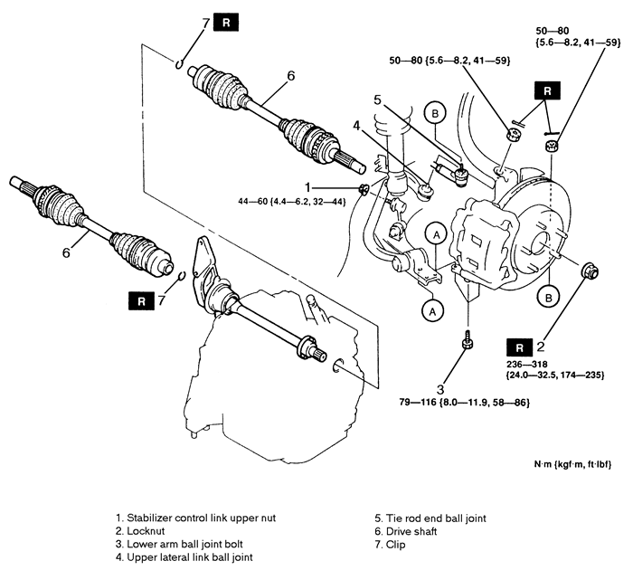
Fig. 1:Halfshaft assembly and related components, exploded view — 1995 Millenia

  1. Raise and safely support the vehicle.
  2. Drain the transaxle fluid.
  3. Remove the stabilizer control link upper nut.
  4. Remove the halfshaft locknut.
  5. Remove the lower arm ball joint bolt.
  6. Disconnect the upper lateral link ball joint. Suspend the axle assembly to prevent damage to the link bushing.
  7. Disconnect the tie-rod end.
  8. LEFT SIDE: separate the halfshaft from the transaxle by prying with a bar inserted between the outer ring and the transaxle. RIGHT SIDE: separate the halfshaft from the joint shaft by hammering on a brass or copper bar inserted between them.
  9. Remove the clip from the halfshaft.

    To install:

  10. Install a NEW clip on the halfshaft so that the opening is facing upwards.
  11. Apply grease to the ends of the halfshaft. Push the halfshaft into the transaxle/joint shaft. After installation, pull the front hub outward to confirm that the halfshaft is securely held by the clip.
  12. Connect the tie-rod end and torque the nut to 41–59 ft. lbs. (50–80 Nm).
  13. Connect the upper lateral link and torque the nut to 41–59 ft. lbs. (50–80 Nm).
  14. Install the lower arm ball joint bolt. Torque to 58–86 ft. lbs. (79–116 Nm).
  15. Install a NEW halfshaft locknut. Torque to 174–235 ft. lbs. (236–318 Nm).
  16. Install the stabilizer control link upper nut and torque to 32–44 ft. lbs. (44–60 Nm).
  17. Fill the transaxle with the proper fluid.
  18. Lower the vehicle.
Joint shaft

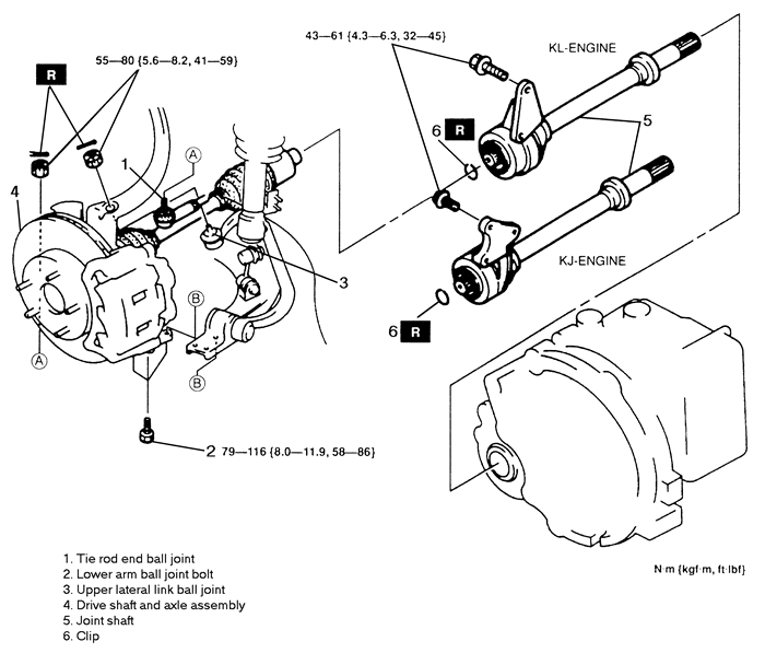
Fig. 2:Joint shaft assembly and related components, exploded view — 1995 Millenia

  1. Raise and safely support the vehicle.
  2. Drain the transaxle fluid.
  3. Disconnect the tie-rod end.
  4. Remove the lower arm ball joint bolt.
  5. Disconnect the upper lateral link ball joint. Suspend the axle assembly to prevent damage to the link bushing.
  6. Separate the right side halfshaft from the joint shaft by hammering on a brass or copper bar inserted between them.
  7. Remove the joint shaft. Remove the clip from the joint shaft.

    To install:

  8. Install a NEW clip to the joint shaft so that the clip opening is facing upwards.
  9. Install the joint shaft and torque the mounting bolts to 32–45 ft. lbs. (43–61 Nm).

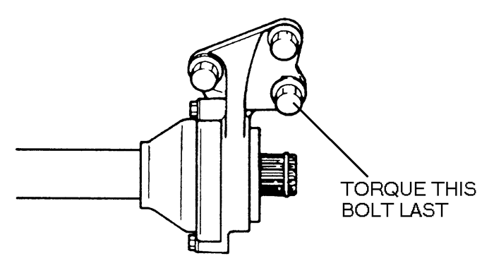
    Fig. 3:Joint shaft mount — 1995–97 Millenia

    NOTE: On the KJ-engine, the bolt on the bottom right of the joint shaft must be tightened last.

  10. Push the halfshaft onto the joint shaft. After installation, pull the front hub outward to confirm that the halfshaft is securely held by the clip.
  11. Connect the upper lateral link ball joint. Torque the nut to 41–59 ft. lbs. (55–80 Nm).
  12. Install the lower arm ball joint bolt and torque to 58–86 ft. lbs. (79–116 Nm).
  13. Connect the tie-rod end. Torque the nut to 41–59 ft. lbs. (55–80 Nm).
  14. Fill the transaxle with the proper fluid.
  15. Lower the vehicle.
1995–97 Miata
  1. Raise and safely support the vehicle. Remove the wheel.
  2. Lock the rear hub by applying the brakes and remove the halfshaft locknut.
  3. Remove the brake caliper assembly.
  4. Remove the lower arm to knuckle bolt.
  5. Matchmark the halfshaft and output shaft for proper alignment before removing the halfshaft.
  6. Pull outward on the hub/knuckle assembly, push the outer CV-joint stub shaft through the hub, and remove the halfshaft. If the halfshaft is stuck in the hub, install the old hub nut to protect the stub shaft threads. Tap on the nut, with only a soft mallet, and remove the halfshaft. Remove the halfshaft from the differential by using a prybar.

    To install:

  7. Install a NEW clip onto the halfshaft. With the ends of the clip facing upward install the halfshaft into the differential with the matchmarks aligned. Verify that the halfshaft is being held in place by the clip.
  8. Insert the other end of the halfshaft through the hub. Join the hub/knuckle assembly to the lower arm and install the bolt and nut. Torque the bolt/nut to 40–47 ft. lbs. (54–63 Nm) on 1995 models and 47–54 ft. lbs. (63–74 Nm) on 1996–97 models.
  9. Install the brake caliper assembly.
  10. Lock the rear hub, install a NEW locknut and torque to 235 ft. lbs. 318 Nm) on 1995 models and 160–216 ft. lbs. (216–294 Nm) on 1996–97 models. Stake the nut after proper torque.
  11. Install the wheel. Lower the vehicle.

Previous Next