Previous Next

Sway Bar

REMOVAL AND INSTALLATION

1993-323 and Protege
  1. Raise and support the vehicle safely. Remove the front wheels.
  2. Remove the 2 stabilizer nuts and remove the upper bushing.
  3. Remove the stabilizer bolt, bushing and retainer.
  4. Remove the bushing, retainer and spacer.
  5. Remove the stabilizer center bushings and bracket and remove the stabilizer bar from the vehicle. Examine the insulators (bushings) carefully for any sign of wear and replace them if necessary.

    NOTE: Check the bushings inside the brackets for wear or deformation. A worn bushing can cause a distinct noise as the bar twists during cornering operation.

    To install:
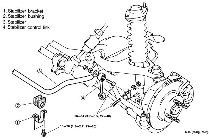
  6. Install stabilizer bar bushings in the correct position.
  7. Temporarily install stabilizer bar brackets. Install the stabilizer bar center bracket bolts and tighten to 27-40 ft. lbs. (38-54 Nm).
  8. Install the bushing retainers and spacers. Install the bolt retainer and bushing.
  9. Install the upper link nuts. Tighten the link nuts so that there is 0.71-0.87 inches (18.1-22.1mm) of thread exposed.
  10. Torque the top link nut to 12-17 ft. lbs. (16-23 Nm).
  11. Install front wheels and lower the vehicle.
  12. Check front wheel alignment.
1995-97 Protege
  1. Disconnect the negative battery cable.
  2. Raise and safely support the vehicle.
  3. Remove the wheels.
  4. Disconnect the tie-rod ends.
  5. Remove the stabilizer control link.
  6. Remove the transverse member.
  7. Remove the three way catalytic converter.
  8. Safely support the engine and remove the engine mounting member.
  9. (M/T) Remove the change control rod and extension bar.
  10. Remove the engine mount bracket.
  11. Support the crossmember by using a jack and remove the mounting nuts and bolts.
  12. Remove the lower arm, front crossmember and the steering gear assembly.
  13. Remove the engine mount.
  14. Remove the stabilizer bracket and bushing.
  15. Remove the stabilizer bar.

    To install:

  16. Replace the stabilizer bar to the vehicle and install the bushings and brackets. Torque the bracket mount bolts to 32-44 ft. lbs. (44-60 Nm).
  17. Install the engine mount, torque nuts to 50-68 ft. lbs. (67-93 Nm).
  18. Replace the steering gear assembly, front crossmember and the lower arm assemblies.
  19. Remove the crossmember support.
  20. Install the engine mount bracket, torque the bolt to 48-65 ft. lbs. (64-89 Nm).
  21. (M/T) Install the extension bar and change control rod.
  22. Install the engine mounting member.
  23. Install the three way catalytic converter.
  24. Install the transverse member.
  25. Install the stabilizer control links.
  26. Install the tie-rod ends.
  27. Connect the negative battery cable.
1993-95 MX3
  1. Raise and safely support the vehicle. Remove the front tire/wheels.
  2. Remove the engine undercover.
  3. Install an engine support device, such as Mazda tool number 49 G017 5A0 or equivalent, to the vehicle.
  4. Remove the tie rod end from the steering knuckle assembly.
  5. On 1.8L engine only, remove the transverse member from under the engine.
  6. Remove the engine mount member.
  7. Disconnect the oxygen sensor connectors and remove the front exhaust pipe from the manifold.
  8. Remove the stabilizer nuts and insulator pad.
  9. Disconnect the steering lines and plug. Remove the steering gear and linkage assembly.
  10. Remove the lower arm and front crossmember assembly bolts, and remove the assembly from the vehicle.
  11. Remove the remaining stabilizer bar bolts, and remove the stabilizer bar.

    To install:

  12. Install the stabilizer bar to the vehicle and loosely install the mounting bolts. If the mounting bushings were removed, make sure that they are replaced to the original positions and that the bushings are aligned with the marks on the bar.
  13. Install the lower arm and front crossmember assembly to the vehicle. Tighten the mounting bolts to 69-93 ft. lbs. (93-127 Nm).
  14. Install the steering gear and linkage. Tighten the mounting nuts to 27-38 ft. lbs. (37-52 Nm), and connect the lines to the steering gear and linkage.
  15. Install the insulator plate and install the stabilizer nuts. Tighten the stabilizer nuts to 32-45 ft. lbs. (43-61 Nm).
  16. Replace the exhaust pipe gaskets and tighten the nuts to 33 ft. lbs. (44 Nm).
  17. Install the engine mount member. Tighten the mounting bolts to 48-65 ft. lbs. (64-89 Nm) and the nuts to 27-38 ft. lbs. (37-52 Nm).
  18. On 1.8L engine only, install the transverse member and tighten the bolts to 69-93 ft.lbs. (93-127 Nm).
  19. Connect the tie rod end to the steering knuckle. Replace the cotter pin.
  20. Remove the engine support device, and install the under engine cover.
  21. Install the wheels and lower the vehicle. Tighten the stabilizer bar bolts to 32-43 ft. lbs. (43-59 Nm).
  22. Bleed the air from the steering system.
1993-97 626 and MX6
  1. Raise and safely support the vehicle. Remove the front tire/wheels.
  2. Remove the engine undercover.
  3. Install an engine support device, such as Mazda tool number 49 G017 5A0 or equivalent, to the vehicle.
  4. Remove the transverse member from under the engine.
  5. Remove the engine mount member.
  6. Disconnect the oxygen sensor connectors and remove the front exhaust pipe from the manifold.
  7. Remove the number one engine mount.
  8. Disconnect the tie rod end ball joint from the steering knuckle assembly.
  9. Disconnect and plug the pressure and return steering lines. Remove the steering gear and linkage assembly.
  10. Support the crossmember, and remove the lower arm and front crossmember assembly mounting bolts.
  11. Remove the stabilizer bracket nuts and insulator pad.
  12. Lower the crossmember assembly from the vehicle.
  13. Remove the remaining stabilizer bar bolts, and remove the stabilizer bar from the crossmember and stabilizer control link.

    To install:

  14. Install the stabilizer bar to the crossmember, and install the mounting bolts. If the mounting bushings were removed, make sure that they are replaced to the original positions and that the bushings are aligned with the marks on the bar. Tighten the stabilizer bar bolts to 27-39 ft. lbs. (37-53 Nm).
  15. Loosely tighten the stabilizer bracket bolts.
  16. Install the lower arm and front crossmember assembly to the vehicle. Tighten the mounting bolts to 69-96 ft. lbs. (93-131 Nm).
  17. Install the steering gear and linkage. Tighten the mounting nuts to 28-38 ft. lbs. (38-51 Nm). Unplug and connect the lines to the steering gear and linkage.
  18. Connect the tie rod end to the steering knuckle. Replace the cotter pin.
  19. Install the number one engine mount.
  20. Replace the exhaust pipe gaskets and nuts, and tighten the nuts to 27-38 ft. lbs. (37-52 Nm). Connect the oxygen sensor connectors.
  21. Install the engine mount member.
  22. Install the transverse member, and tighten the bolts to 69-96 ft. lbs. (94-131 Nm).
  23. Remove the engine support device and install the under engine cover.
  24. Install the wheels and lower the vehicle.
  25. Tighten the stabilizer bracket bolts to 27-39 ft. lbs. (37-53 Nm).
  26. Check the front wheel alignment.
  27. Bleed the power steering system.
1993-95 929
  1. Raise and support the vehicle safely. Remove the front wheels.
  2. Remove the 2 stabilizer nuts and remove the upper bushing.
  3. Remove the stabilizer bolt, bushing and retainer.
  4. Remove the bushing, retainer and spacer.
  5. Remove the stabilizer center bushings and bracket and remove the stabilizer bar from the vehicle. Examine the insulators (bushings) carefully for any sign of wear and replace them if necessary.

    NOTE: Check the bushings inside the brackets for wear or deformation. A worn bushing can cause a distinct noise as the bar twists during cornering operation.

    To install:

  6. Install stabilizer bar bushings in the correct position.
  7. Temporarily install stabilizer bar brackets. Install the stabilizer bar center bracket bolts and tighten to 32-40 ft. lbs. (44-54 Nm).
  8. Install the bushing retainers and spacers. Install the bolt retainer and bushing.
  9. Install the upper link nuts. Tighten the link nuts so that there is 0.71-0.87 inches (18.1-22.1mm) of thread exposed.
  10. Torque the stabilizer link bolt to 32-39 ft. lbs. (44-53 Nm).
  11. Install front wheels and lower the vehicle.
  12. Check front wheel alignment.
1995-97 Millenia
  1. Disconnect the negative battery cable and wait at least 90 seconds before performing any work.
  2. Raise and safely support the vehicle.
  3. Remove the splash shields.
  4. Remove the transverse member.
  5. Disconnect the power steering return hose and pressure pipe.
  6. Remove the intermediate steering shaft bolt.
  7. Support the engine from the top and remove the engine mount member.
  8. Remove the bolts for engine mount No. 1.
  9. Remove the lower strut mounting bolt.
  10. Disconnect the stabilizer control link.
  11. Support the crossmember using a jack and remove the crossmember mounting nuts. Lower the crossmember to gain clearance and remove the stabilizer bracket and bushing. Remove the stabilizer bar.

    To install:

  12. Replace the stabilizer bar assembly to the vehicle and install bushings and brackets, torque the nut to 32-44 ft. lbs. (44-60 Nm), then install the crossmember mounting bolts.
  13. Connect the stabilizer control link, torque the nut to 32-44 ft. lbs. (44-60 Nm).
  14. Install the strut lower mounting bolt and torque to 73-101 ft. lbs. (98-137 Nm).
  15. Install the No. 1 engine mount bolts and torque to 32-44 ft. lbs. (44-60 Nm).
  16. Install the engine mount member, torque the bolts to 50-68 ft. lbs. (67-93 Nm) and the nuts to 55-77.3 ft. lbs. (75-104 Nm). Remove the engine support tool.
  17. Install the intermediate steering shaft bolt, torque to 13-19 ft. lbs. (18-26 Nm).
  18. Connect the power steering pressure pipe and return hose.
  19. Install the transverse member.
  20. Install the splash shields.
  21. Lower the vehicle. Reconnect the negative battery cable. Check the power steering fluid and fill to proper level, bleed if necessary. Check the front end alignment.
1993-97 Miata
Fig. 1:Sway bar (exploded view) -- 1993-97 Miata

  1. Raise and support the vehicle safely.
  2. Remove the splash shield.
  3. Remove the two stabilizer nuts, and remove the upper bushing.
  4. Remove the stabilizer bolt, bushing and retainer.
  5. Remove the stabilizer bar from the vehicle. Examine the insulators (bushings) carefully for any sign of wear and replace them if necessary.

    NOTE: Check the bushings inside the brackets for wear or deformation. A worn bushing can cause a distinct noise as the bar twists during cornering operation.

    To install:

  6. Install stabilizer bar bushings in the correct position.
  7. Temporarily install stabilizer bar brackets.
  8. Install the bolt retainer and bushing.
  9. Install the splash shield.
  10. Lower the vehicle.
  11. Tighten the stabilizer bar brackets bolts to 14-19 ft. lbs. (18-26 Nm), and the control link mounting bolts to 27-39 ft. lbs. (37-53 Nm).
  12. Check front wheel alignment.
1993-95 RX7
  1. Raise and support the vehicle safely. Remove the front wheels and the undercover.
  2. Remove the stabilizer control link nut and the stabilizer plate mount bolts. Remove the bushings.
  3. Remove the stabilizer bar. If necessary, remove the stabilizer control link.
  4. Installation is the reverse of removal. Check front wheel alignment.
 
Previous Next