| Fig. 1: Silent shaft belt timing marks — 1.8L
engine
|
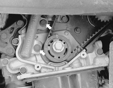
| Fig. 2: Checking the silent shafts for proper positioning
|
| Fig. 3: Timing belt timing mark alignment — 1.8L
engine
|
To install:
NOTE: There is a possibility to align all timing marks and have the oil pump sprocket and silent shaft out of time, causing an engine vibration during operation. If the following step is not followed exactly, there is a 50 percent chance that the silent shaft alignment will be 180 degrees off.
NOTE: Always rotate the crankshaft in a clockwise direction. Make a mark on the back of the timing belt indicating the direction of rotation so it may be reassembled in the same direction if it is to be reused.
| Fig. 4: Exploded view of the timing belt and sprockets — 1990–94
2.0L engines
|
To install:
| Fig. 5: Align the camshaft sprocket so marks face
each other and are in alignment with the top surface of the cylinder
head — 1990–94 2.0L engine
|
| Fig. 6: Align the crankshaft timing mark and the
oil pump sprocket timing mark — 1990–94 2.0L
engine
|
| Fig. 7: Timing marks in alignment — 1990–94
2.0L engine
|
NOTE: When tightening the bolt of the tensioner, ensure that the tensioner pulley shaft does not rotate with the bolt. Allowing it to rotate with the bolt can cause excessive tension on the belt.
NOTE: Both camshaft sprockets are used for the intake and exhaust camshafts and are provided with 2 timing marks. When the sprocket is mounted on the exhaust camshaft, use the timing mark on the right with the dowel pin hole on top. For the intake camshaft sprocket, use the 1 on the left with the dowel pin hole on top.
NOTE: The above step assures that the oil pump socket is in correct orientation to the silent shafts. This step must not be skipped or a vibration may develop during engine operation.
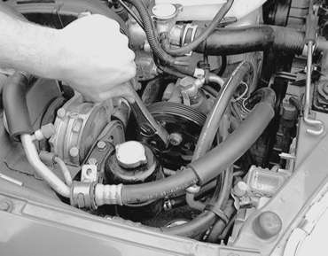
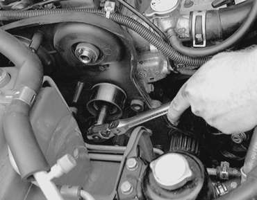
| Fig. 8: Unfasten the power steering pump retaining
bolts
|
| Fig. 9: Engine timing system parts identification — 1995–98
2.0L non-turbo engine
|
NOTE: If the timing belt is going to be reused, mark the direction of rotation on the belt with an arrow. Install the belt in the same direction.
| Fig. 10: If you are going to reinstall the old belt,
mark the direction of rotation for installation purposes
|
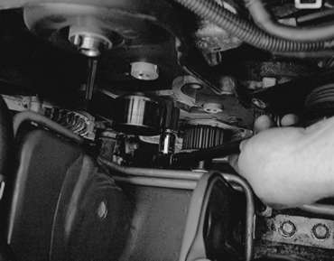
| Fig. 11: Loosen the timing belt tensioner bolts (see
arrows) . . .
|
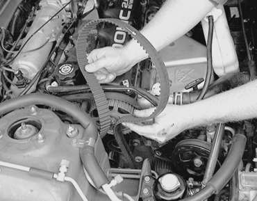
| Fig. 12: . . . then remove the timing belt from the
engine
|
| Fig. 13: Unfasten the tensioner retaining bolts .
. .
|
| Fig. 14: Remove the timing belt tensioner
|
| Fig. 15: Remove the camshaft sprocket retaining bolt
. . .
|
| Fig. 16: . . . then remove the camshaft sprocket
from the vehicle
|
WARNING
Do not rotate the crankshaft or the camshafts while the belt is removed.
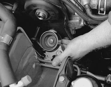
| Fig. 17: If necessary to remove the idle pulley,
unfasten the retaining bolt
|
| Fig. 18: . . . then remove the idle pulley, if necessary
|
| Fig. 19: Unfasten the tensioner pulley retaining
bolt . . .
|
| Fig. 20: . . . then remove the tensioner pulley
|
To install:
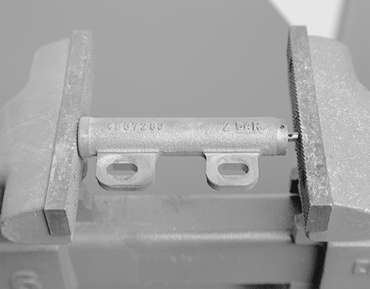
| Fig. 21: Compress the tensioner in a vise — 1995–98
2.0L non-turbo engine
|
| Fig. 22: Once the tensioner is removed from the vehicle,
plate it in a suitable vise
|
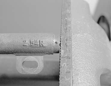
| Fig. 23: Use the vise to carefully compress the plunger
into the body
|
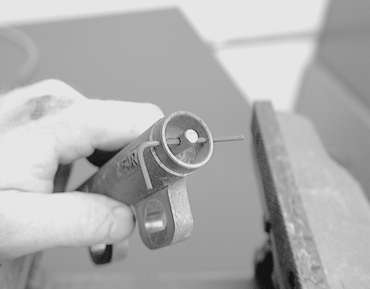
| Fig. 24: When the plunger of the tensioner is fully
compressed, insert a pin through the body to hold it
|
| Fig. 25: Engine timing marks — 1995–98
2.0L non-turbo engine
|
NOTE: If the timing belt is to be reused, mark the direction of rotation on the flat side of the belt with an arrow.
WARNING
Do not rotate the camshafts or the crankshaft while the timing belt is removed.
| Fig. 26: Timing belt routing and component identification — 1995–98
2.0L turbo engine
|
To install:
WARNING
Do not compress the pushrod too quickly, damage to the pushrod can occur.
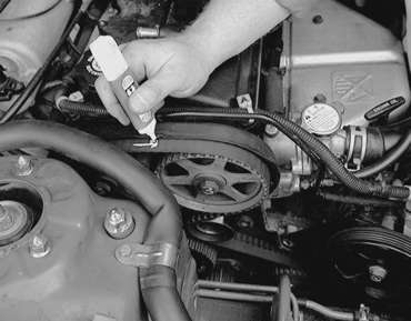
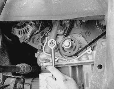
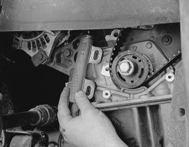
| Fig. 27: After the timing mark on the oil pump sprocket
is lined up, remove the block plug and insert a screwdriver to assure
proper alignment
|
| Fig. 28: Keep the timing belt in position using a
bulldog clip
|
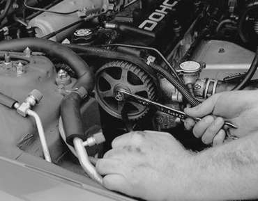
| Fig. 29: Use 2 wrenches to align the marks with the
top of the cylinder head
|
| Fig. 30: Use a torque wrench and adapter to apply
tension to the timing belt — 1995–98 2.0L turbo
engine
|
| Fig. 31: View of the proper timing mark alignment — 1995–98
2.0L turbo engine
|
NOTE: If timing belts are going to be reused, mark the direction of rotation on the belt. This will ensure the belt is reinstalled in same direction, extending belt life.
| Fig. 32: Exploded view of the inner (B) timing belt
and related components — 2.4L engine
|
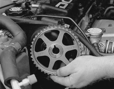
| Fig. 33: You will probably have to use a special
tool to remove the crankshaft pulley bolt — 2.4L engine
|
| Fig. 34: If you're having trouble removing the sprocket,
you may have to use a suitable puller
|
To install:
Inspect the timing belts in detail for any flaw or wear. Check the sprockets and tensioner for wear. The sprocket teeth should be well defined, not rounded and the valleys between the teeth should be clean. Turn both tensioner pulleys and check for any signs of bearing wear. If sprockets or pulleys show any sign of wear, they must be replaced.
WARNING
Do not spray or immerse the sprockets or tensioners in cleaning solvent.
The sprocket may absorb the solvent and transfer it to the belt. The tensioners
are internally lubricated and the solvent will dilute or dissolve the lubricant.
NOTE: There is a possibility to align all timing marks and have the oil pump sprocket and silent shaft out of time, causing an engine vibration during operation. If the following step is not followed exactly, there is a 50 percent chance that the silent shaft alignment will be 180 degrees off.
| Fig. 35: Proper timing component alignment points — 2.4L
engines
|
NOTE: Do not manually overtigthen the belt or it will howl.
| Fig. 36: Timing belt cover retainer specifications — 2.4L
engine
|