Previous Next

TESTING

Except 1995–98 2.0L Non-Turbo Engine
  1. Detach the air flow sensor electrical connector.

    Fig. 1: IAT sensor terminal identification — 1990–94 vehicles

    Fig. 2: IAT sensor terminal identification — 1995–98 2.0L turbo and 2.4L engines

    Fig. 3: Measure the intake air temperature sensor resistance while heating it with a hair drier

  2. If equipped with non-turbo engines, measure the resistance between terminals No. 4 and No. 6 of the electrical connector.
  3. If equipped with turbo engine, measure the resistance between terminals No. 6 and No. 8 of the sensor electric connector.
  4. Compare test readings to specifications:
    1. Sensor temperature of 32°F (0°C) — 5.3–6.7 kilo-ohms
    2. Sensor temperature of 68°F (20°C) — 2.3–3.0 kilo-ohms
    3. Sensor temperature of 176°F (80°C) — 0.30–0.42 kilo-ohms
  5. Measure the sensor resistance while heating the sensor area with a hair dryer. As the temperature of the sensor increases, sensor resistance should become smaller.
  6. If the measured resistance deviates from the standard value or the resistance remains unchanged, replace the air flow sensor assembly.
1995–98 2.0L Non-Turbo Engine
  1. Detach the IAT sensor connector.
  2. If necessary, you can remove the sensor to test it.
  3. Use a DVOM to measure the resistance between the sensor terminals and compare with the following specifications:
    1. At 77°F (25°C), the resistance should be 9–11 kilo-ohms.
    2. At 212°F (100°C), the resistance should be 0.6–0.8 ohms.

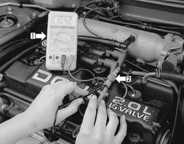
      Fig. 4: Use an ohmmeter (1) to measure the resistance of the IAT sensor (2). Note that this sensor is within specifications

  4. If the resistance is not within the specified range, replace the sensor.
  5. If removed, install the sensor. Attach the connector.

Previous Next