Previous Next

Clutch Disc and Pressure Plate

REMOVAL & INSTALLATION

1990–94 Vehicles
  1. Disconnect the negative battery cable. Raise and safely support the vehicle.
  2. Remove the transaxle assembly from the vehicle.
  3. Remove the pressure plate attaching bolts, pressure plate and clutch disc. If the pressure plate is to be reused, loosen the bolts in a diagonal pattern, 1 or 2 turns at a time. This will prevent warping the clutch cover assembly.
  4. Remove the return clip and the pressure plate release bearing. Do not use solvent to clean the bearing.
  5. Inspect the clutch release fork and fulcrum for damage or wear. If necessary, remove the release fork and unthread the fulcrum from the cable.
  6. Carefully inspect the condition of the clutch components and replace any worn or damaged parts.

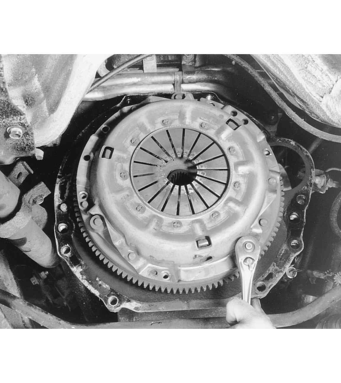
    Fig. 1: Exploded view of the clutch cover and disc — 1990–94 vehicles

    Loosen and remove the clutch and pressure plate bolts evenly, a little at a time . . .

    . . . then carefully remove the clutch and pressure plate assembly from the flywheel

    Check across the flywheel surface, it should be flat

    If necessary, lock the flywheel in place and remove the retaining bolts . . .

    . . . then remove the flywheel from the crankshaft in order replace it or have it machined

    Upon installation, it is usually a good idea to apply a threadlocking compound to the flywheel bolts

    Be sure that the flywheel surface is clean, before installing the clutch

    Install a clutch alignment arbor, to align the clutch assembly during installation

    You may want to use a threadlocking compound on the clutch assembly bolts

    Be sure to use a torque wrench to tighten all bolts

    To install:

  7. Inspect the flywheel for heat damage or cracks. Resurface or replace the flywheel as required. Install the flywheel using new bolts.
  8. Install the fulcrum and tighten to 25 ft. lbs. (35 Nm). Install the release fork. Apply a coating of multi-purpose grease to the point of contact with the fulcrum and the point of contact with the release bearing. Apply a coating of multi-purpose grease to the end of the release cylinder's push rod and the push rod hole in the release fork.

    NOTE: When installing the clutch, apply grease to each part, but be careful not to apply excessive grease; excessive grease will cause clutch slippage and shudder.

  9. Apply multi-purpose grease to the clutch release bearing. Pack the bearing inner surface and the groove with grease. Do not apply grease to the resin portion of the bearing. Place the bearing in position and install return clip.
  10. Apply a coating of grease to the clutch disc splines and then use a brush to rub it in the grooves. Using a universal clutch disc alignment tool, position the clutch disc on the flywheel. Install the retainer bolts and tighten a little at a time, in a diagonal sequence. Tighten them to a final torque of 16 ft. lbs. (22 Nm). Remove the aligning tool.
  11. Install the transaxle assembly and check for proper clutch operation.
1995–98 Vehicles
2.0L NON-TURBO ENGINE
  1. Remove the transaxle from the vehicle.
  2. Unscrew the fittings, then remove the clutch oil tube. Plug or cap the ends to prevent contamination from entering the line.
  3. Remove the release (slave) cylinder.
  4. Unfasten the retaining bolts, then remove the clutch and flywheel assembly. Remove the driveplate.
  5. Remove the clutch release bearing.
  6. Remove the clutch release lever.
  7. Remove the clutch control equip stud.
  8. Remove the boot.

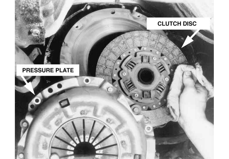
    Fig. 2: Exploded view of the clutch system components — 1995–98 2.0L non-turbo engines

    To install:

  9. Install the boot assembly.
  10. Install the clutch control equip stud.
  11. Apply a suitable grease to the clutch release lever, as shown in the accompanying figure. Install the clutch release lever.

    Fig. 3: Before installation, apply grease to the ends of the clutch release lever

  12. Install the clutch release bearing.
  13. Apply a suitable grease to the clutch disc splines, squeezing it in place with a brush. Install the driven plate, and the clutch and flywheel assembly.
  14. Install the clutch release (slave) cylinder.
  15. Install the clutch oil tube.
  16. Install the transaxle in the vehicle.
2.0L TURBO AND 2.4L ENGINES
  1. Remove the transaxle from the vehicle.
  2. Unscrew the fittings, then remove the clutch oil tubes.
  3. Unfasten the retaining bolt, then remove the clutch oil fluid chamber.
  4. Remove the clutch release (slave) cylinder union bolt, the gaskets and the union.
  5. Remove the valve plate and valve plate spring.
  6. Remove the clutch release (slave) cylinder.
  7. Unfasten the clutch cover retaining bolts, slowly and evenly in a criss-cross pattern, then remove the clutch cover. Remove the clutch disc.
  8. Unfasten the return clip, then remove the clutch release bearing.
  9. Slide the release fork in the direction of the arrow shown in the accompanying figure, then detach the fulcrum from the clip to remove the release fork. Be careful not to cause damage to the clip by pushing the fork in any other direction or removing it with force. Exploded view of the clutch and related components — 1995–98 2.0L turbo and 2.4L engines

    Fig. 4: You must remove the release fork by sliding it in the correct direction, or you may damage it

  10. Remove the release fork boot and fulcrum.

    To install:

  11. Install the fulcrum and the release fork boot.
  12. Apply grease to the areas shown on the clutch release fork, then install the fork.

    Fig. 5: Apply a suitable grease to the areas designated on the release fork

  13. Before installation, apply a suitable grease to the areas shown on the clutch release bearing.

    Fig. 6: You must apply grease to the areas shown on the release bearing

  14. Install the return clip.
  15. Apply a suitable grease to the clutch disc splines, squeezing it in plate with a brush. Install the clutch disc, using a suitable guide to position the disc on the flywheel.
  16. Install the clutch cover.
  17. Install the clutch release (slave) cylinder.
  18. Install the valve plate spring and valve plate.
  19. Install the gasket, union, gasket and union bolt on the release cylinder.
  20. Install the clutch oil fluid chamber. Uncap or unplug the clutch oil tubes, then attach them and tighten the fittings to 11 ft. lbs. (15 Nm).
  21. Install the transaxle assembly.

Previous Next