Engine size, transaxle type, whether the joint is an inboard or outboard joint,
even which side of the vehicle is being serviced could make a difference in
joint type. Be sure to properly identify the joint before attempting joint or
boot replacement. Look for identification numbers at the large end of the boots
and/or on the end of the metal retainer bands.
The 2 types of joints used are the Birfield Joint, (B.J.) and the Tripod Joint
(T.J.). Special grease and clamps are used with these joints and is normally
supplied with the replacement joint and/or boot kit. Do not use regular chassis
grease.
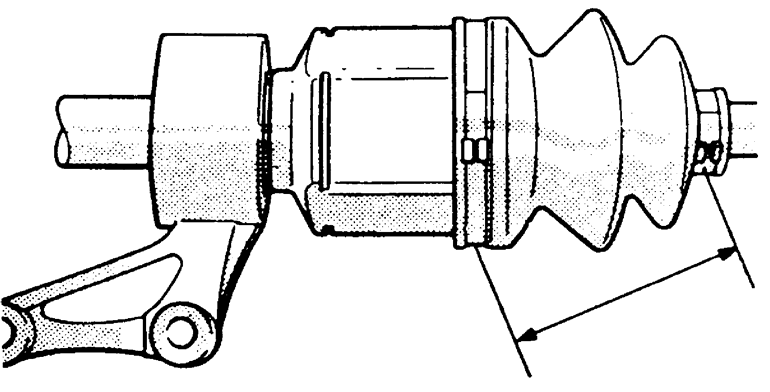
Correct installation of the CV-boot is essential for its longevity. A specification
is given for the distance between the large and small boot bands. This is so
the boot will not be installed either too loose or too tight, which could cause
early wear and cracking, allowing the grease to get out and water and dirt in,
leading to early joint failure.
Both of the halfshaft boots are going to be removed from the T.J. case side
of the halfshaft.
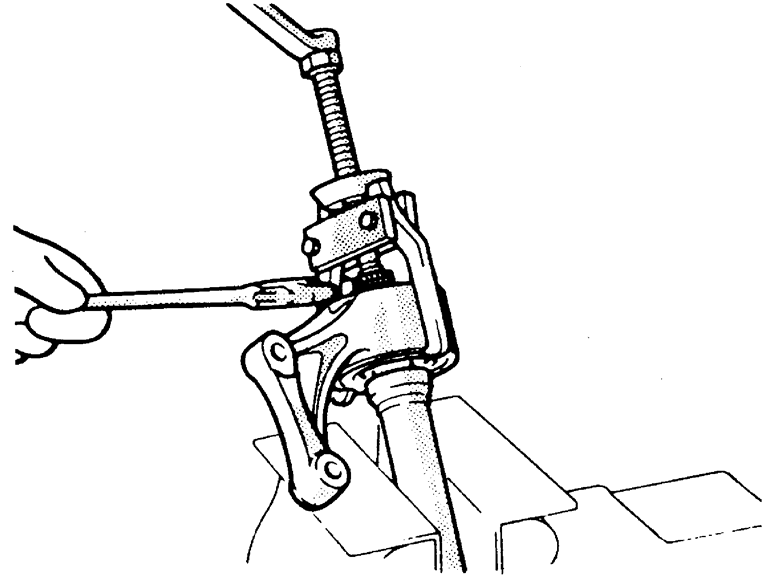
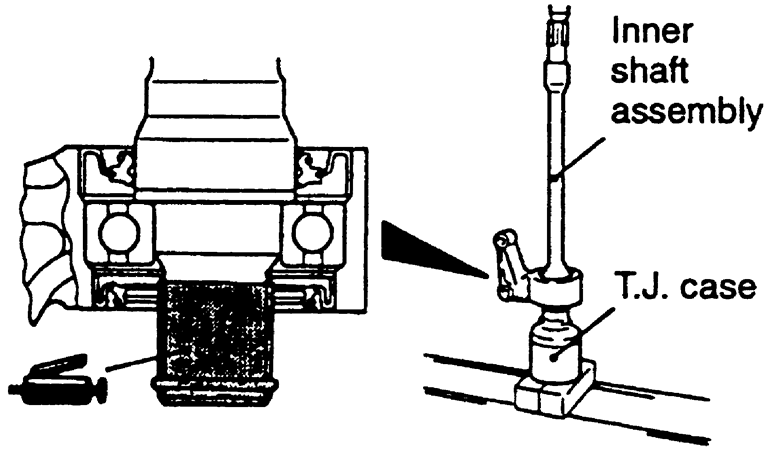
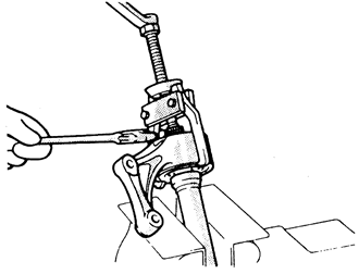
- Disconnect the negative battery cable. Remove the halfshaft from the vehicle.
- Remove the T.J. boot bands from the boot. Side cutter pliers can be used
to cut off the metal retaining bands. Remove the T.J. case from the halfshaft.
- Remove the snapring next to the tripod joint spider assembly from the halfshaft
with snapring pliers. Remove the spider assembly from the shaft.
NOTE: Do not disassemble the spider and use care in handling.
- If the boot is be reused, wrap vinyl tape around the spline part of the
shaft so the boot will not be damaged when removed. Remove the dynamic damper,
if used, and boots from the shaft.
| Fig. 1: Set the boot so the bands are at correct
distance
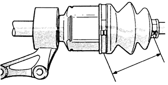
|
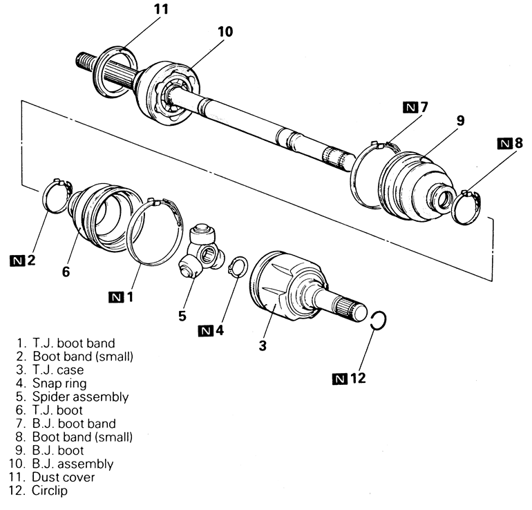
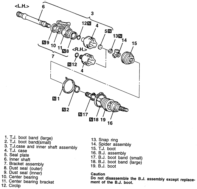
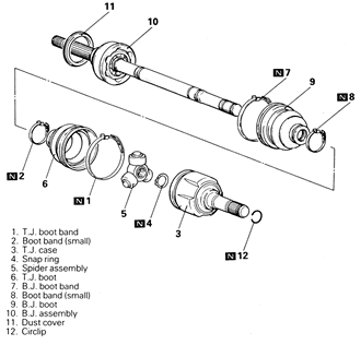
| Fig. 2: Exploded view of front halfshaft
|
To install:
- Double check that the correct replacement parts are being installed. Wrap
vinyl tape around the splines to protect the boot and install the boots and
damper, if used, in the correct order.
- Fill the inside of the boot with the specified grease. Often the grease
supplied in the replacement parts kit is meant to be divided in half, with
half being used to lubricate the joint and half being used inside the boot.
Keep grease off the rubber part of the dynamic damper (if used).
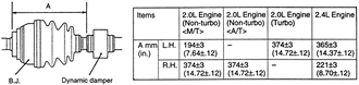
- Secure the boot bands with the halfshaft in a horizontal position. Make
sure the boot span on the halfshaft is 3.23–3.47 in. (82–88mm)
in length.
- Install halfshaft into vehicle.
- Disconnect the negative battery cable.
- Remove the halfshaft from the vehicle.
- Remove the large and small T.J. boot bands. You can use a pair of side cutters
or a prytool to remove the bands.
- Remove the T.J. case from the B.J. assembly, then wipe the grease from inside
of the T.J. case.
- Remove the retaining circlip.
- Use a pair of snapring pliers to remove the snapring from the driveshaft,
then carefully take the spider assembly out of the driveshaft. Clean the spider
but be careful not to damage it, and do not disassemble it.
- Wipe the grease from the splines, then remove the T.J. boot. If the boot
is going to be reused, wrap plastic tape around the driveshaft spline so the
boot is not damaged when it is removed.
- Unfasten the damper band, then remove the dynamic damper.
- Remove the B.J. assembly.
- Use a prytool to remove the small and large bands from the B.J. boots, then
remove the B.J. boot.
NOTE: Do not disassemble the B.J. assembly, except the
replacement of the B.J. boot.
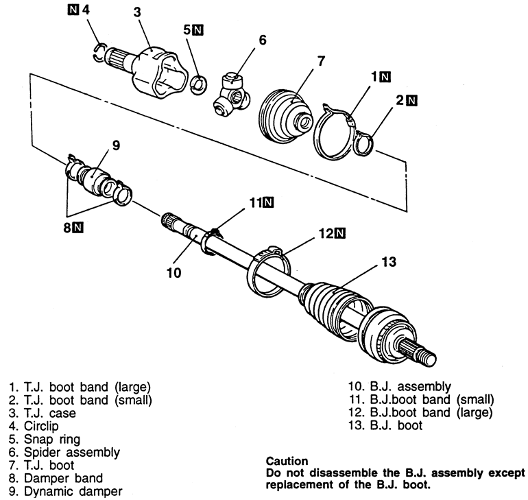
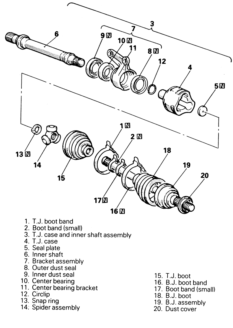
| Fig. 3: Exploded view of the halfshaft assembly — 1995–98
FWD vehicles

|
To install:
- Install the B.J. boot large and small boot bands, as follows:
- Wrap plastic tape around the spline part on the driveshaft, then install
small B.J. boot band and B.J. boot.
- Install the smaller side of the B.J. boot band so that one shaft groove
can be seen.
- Turn the adjusting bolt of the boot band crimper tool to adjust the
opening dimension to the standard value of 0.114 in. (2.9mm). When more
than 0.114 in. (2.9mm) screw in the adjusting bolt, when less that 0.114
in. (2.9mm), loosen the adjusting bolt less that one full turn.
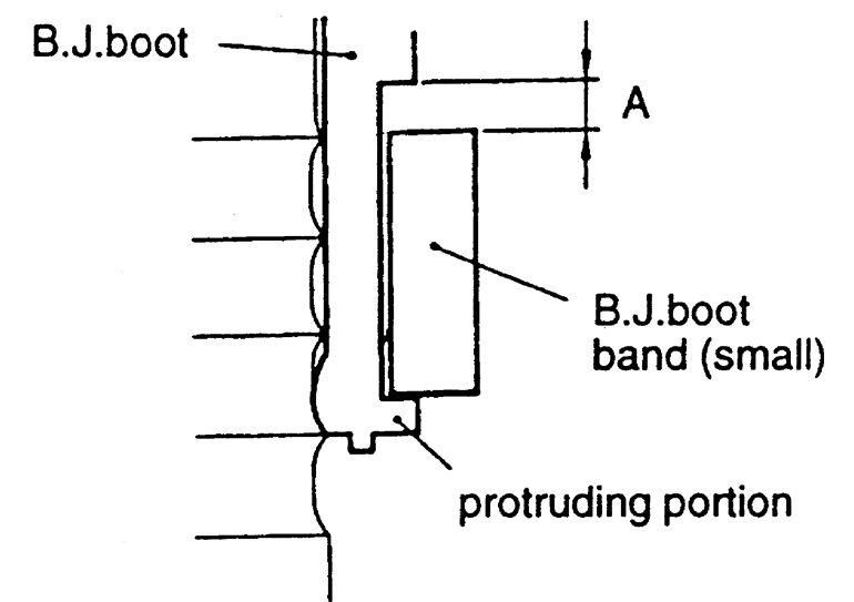
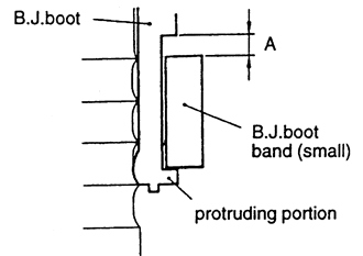
- Place the small boot band along the protruding portion, and install
it so that there is some clearance (A) along the other side. Hold the
driveshaft perpendicularly, then use a suitable boot band crimping tool
to crimp the small boot band until the tool touches the stopper.
| Fig. 4: Install the small boot so there is some
clearance (A), as shown
|
- Check that the crimped width is within 0.094–0.110 in. (2.4–2.8mm).
- Check that the B.J. boot band is secured correctly. If not, repeat the
last 3 steps.
- Apply the proper amount of grease the boot. For 2.0L non-turbo engines,
the proper amount is 3.88 oz. (110 g) and for 2.0K turbo and 2.4L engines,
the proper amount is 4.59 ox. (130 g).
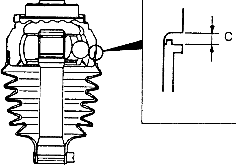
- Install the B.J. boot to adjust the clearance (C) between the B.J. boot
end and the stepped phase of the B.J. housing is within 0.004–0.061
in. (0.1–1.55mm).
| Fig. 5: Install the boot to adjust the clearance
between the boot end and the stepped part of the housing

|
- Adjust the opening dimension (W) to the standard value, which is 0.126
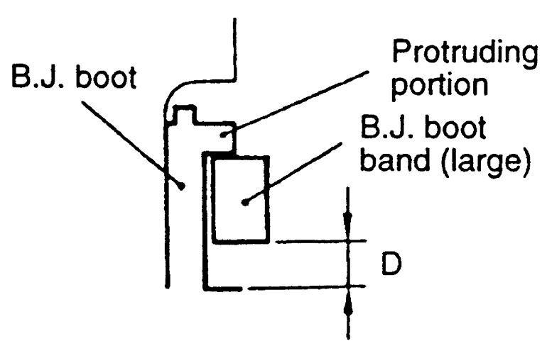
in. ( 3.2mm).
- Place the large B.J. boot band along the protruding part, then install
it so there is some clearance along the other side. Use a boot band crimping
tool to properly crimp the large band.
| Fig. 6: Once the large B.J. boot band is installed,
there should be some clearance as shown

|
- Check that the crimped width is between 0.094–0.110 in. (2.4–2.8mm).
Make sure the boot band is secured properly. If not, repeat the last 3
steps.
- Install the B.J. assembly.
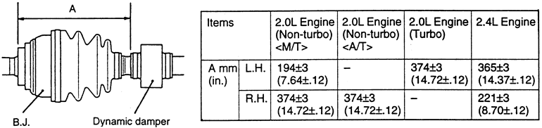
- Install the dynamic damper assembly, and compare with the specifications
shown in the accompanying figure. Install the damper band.
| Fig. 7: Install the dynamic damper as shown, making
sure the proper specifications are met
|
- Install the T.J. boot.
NOTE: The grease supplied in the repair kit should be equally
divided in half for use at the joint and inside the boot.
- Install the spider assembly to the shaft from the direction of the spline
beveled section. After applying the proper amount of grease to the T.J. case
, insert the driveshaft, then apply grease once again. The grease specifications
are:
- 2.0L non-turbo engines: 3.70 oz. (105 g).
- 2.0L turbo and 2.4L engines: 4.23 oz. (120 g).
- Install the retaining snapring and circlip.
- Install the T.J. boot bands by setting the boot bands at the specified distance
in order to adjust the amount of air inside the boot, then tighten the bands
securely. The standard value is 3.03–3.27 in. (77–83 mm).
- Install the halfshaft in the vehicle, as outlined earlier.
- Connect the negative battery cable.
- Disconnect the negative battery cable. Remove the halfshaft from the vehicle.
- Remove the T.J. large and small boot bands. Remove the T.J. case from inner
shaft assembly.
- Remove the snapring next to the tripod joint spider assembly from the halfshaft
with snapring pliers. Remove the spider assembly from the shaft.
NOTE: Do not disassemble the spider and use care in handling.
- If the boot is be reused, wrap vinyl tape around the spline part of the
shaft so the boot will not be damaged when removed.
- Remove the inner and the outer dust seals from the center support bearing
assembly. Remove the center bearing from the shaft.
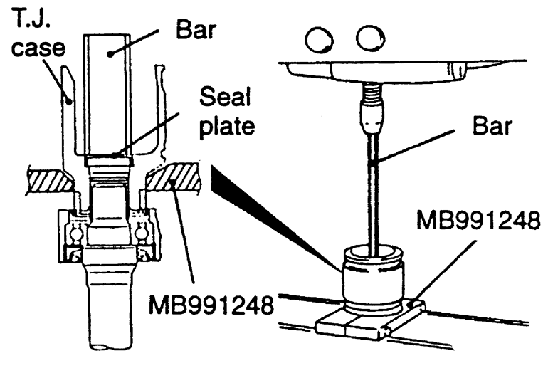
- Remove the inner shaft assembly, together with the seal plate, from the
T.J. case. Using puller tool, remove the inner shaft from the center bearing
bracket.
| Fig. 8: Exploded view of the front halfshaft and
related components — 1990–94 FWD vehicle

|
| Fig. 9: Use a suitable jawed puller tool to remove
the inner shaft from the center bearing bracket
|
To install:
- Apply multi-purpose grease to the center bearing and inside the center bearing
bracket. Using proper size driver, press fit the center bearing into the center
bearing bracket.
- Apply multi-purpose grease to the rear surfaces of both dust seals and install.
Use a pipe to hold the inner race of the center bearing and force the inner
shaft into place.
- Install the boots in place. Apply grease to the inner shaft splines, then
press fit it into the T.J. case. Press the seal plate into the T.J. case.
- Fill the join and the boot with the specified grease, enclosed in the repair
kit. Divide the grease in half between the joint and the boot. Keep grease
off the rubber part of the dynamic damper (if used).
- Secure the boot bands with the halfshaft in a horizontal position. Make
sure the boot span on the halfshaft is 3.23–3.47 in. (82–88mm)
in length.
- Install halfshaft into vehicle.
| Fig. 10: Exploded view of the left-side halfshaft assembly — 1995–98
AWD vehicles

|
- Disconnect the negative battery cable.
- Remove the halfshaft from the vehicle.
- Remove the large and small T.J. boot bands. You can use a pair of side cutters
or a prytool to remove the bands.
- Remove the T.J. case and inner shaft assembly (if equipped).
- Remove the T.J. case from the B.J. assembly, then wipe the grease from inside
of the T.J. case.
- Remove the seal plate.
- With the inner shaft in a soft-jawed vise, use a suitable inner shaft removal
tool, to remove the inner shaft, along with the seal plate, from the T.J.
case. Remove the inner shaft from the bracket using a jawed puller.
| Fig. 11: Use a inner shaft removal tool to remove
the inner shaft and seal plate from the T.J. case
|
- Remove the bracket assembly.
- Remove the outer and inner dust seals.
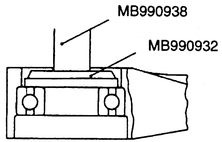
- Remove the center bearing using the special tools shown in the accompanying
figure.
| Fig. 12: There is a special plate and adapter tool
necessary to remove and install the center bearing

|
- Rem,ove the center bearing bracket.
- Remove the retaining circlip.
- Use snapring pliers to remove the snapring from the driveshaft, then take
the spider assembly from the driveshaft. Carefully clean the spider, being
careful damage or disassemble the driveshaft.
- Wipe the grease from the splines, then remove the T.J. boot. If the boot
is going to be reused, wrap plastic tape around the driveshaft spline so the
boot is not damaged when it is removed.
- Remove the B.J. assembly.
- Use a prytool to remove the small and large bands from the B.J. boots, then
remove the B.J. boot.
NOTE: Do not disassemble the B.J. assembly, except the
replacement of the B.J. boot.
To install:
- Install the B.J. boot, and large and small boot bands, as follows:
- Wrap plastic tape around the spline part on the driveshaft, then install
small B.J. boot band and B.J. boot.
- Install the smaller side of the B.J. boot band so that one shaft groove
can be seen.
- Turn the adjusting bolt of the boot band crimper tool to adjust the
opening dimension to the standard value of 0.114 in. (2.9mm). When more
than 0.114 in. (2.9mm) screw in the adjusting bolt, when less that 0.114
in. (2.9mm), loosen the adjusting bolt less that one full turn.
- Place the small boot band along the protruding portion, and install
it so that there is some clearance (A) along the other side. Hold the
driveshaft perpendicularly, then use a suitable boot band crimping tool
to crimp the small boot band until the tool touches the stopper.
- Check that the crimped width is within 0.094–0.110 in. (2.4–2.8mm).
- Check that the B.J. boot band is secured correctly. If not, repeat the
last 3 steps.
- Install the repair kit grease, 3.35 oz. (95 g) to the boot. Install
the B.J. boot to adjust the clearance between the boot end and the stepped
phase of the housing within 0.004–0.061 in. (0.10–1.55mm).
- Adjust the opening dimension (W) to 0.126 in. (3.2mm).
- Place the large B.J. boot band along the protruding part, then install
it so there is some clearance along the other side. Use a boot band crimping
tool to properly crimp the large band.
- Check that the crimped width is between 0.094–0.110 in. (2.4–2.8mm).
Make sure the boot band is secured properly. If not, repeat the last 3
steps.
- Install the B.J. assembly.
- Install the T.J. boot.
- Install the spider assembly to the shaft from the direction of the splined
beveled section.
- Use the special tools to install the center bearing. Install the center
bearing bracket.
- Install the dust seals as follows:
- Apply a multi-purpose grease to the rear surfaces of the inner and outer
dust seals. For the inner seal, apply 0.25–0.35 oz. (7–10
g) and for the outer seal, apply 0.14–0.21 oz. (4–6 g) or
grease.
- Use a seal adapter and press assembly to install the dust seal so that
its surface is even with the center bearing bracket.
- Apply the grease to the lip of each dust seal, but when applying the
grease, make sure it doesn't get on anything outside the lip.
- Install the bracket assembly.
- Use a proper sized adapter to install the inner shaft.
- Install the seal plate and T.J. case.
- Install the T.J. case and inner shaft, as follows:
- Apply multi-purpose grease to the inner shaft spline then press fit
the shaft into the T.J. case.
| Fig. 13: After applying suitable grease, press
fit the inner shaft into the T.J. case

|
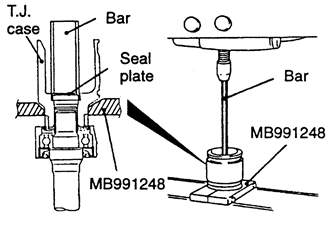
- Use an inner shaft removal tool to support the T.J. case, then use a
1.18 in. (30mm) diameter pipe to press the seal plate into the T.J. case.
| Fig. 14: Hold the case with the shaft removal
tool, then use pipe to press the seal plate into the case
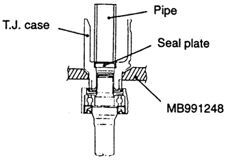
|
- Fill the T.J. case with 3.70 oz. (105 g) or the grease supplied in the
repair kit. The grease should be divided in half for use at the joint
and inside the boot.
- Install the small and large T.J. boots, as follows:
- Set the boot bands at the proper distance to adjust the amount of air
inside the boot, then tighten the boot band securely. The standard value
is 3.03–3.27 in. (77–83mm).
- Install the halfshaft in the vehicle.