Previous Next

FRONT SUSPENSION

MacPherson Strut

REMOVAL & INSTALLATION

1990–94 Vehicles
  1. Disconnect the negative battery cable.
  2. Raise and safely support vehicle.
  3. Remove the wheel and tire assembly.
  4. Remove the brake hose and tube bracket retainer bolt and bracket from the front strut. Do not pry the brake hose and tube clamp away when removing.
  5. If equipped with ABS, disconnect the front speed sensor mounting clamp from the strut.
  6. Support the lower arm using floor jack or equivalent. Remove the lower strut to knuckle bolts. Once the mounting bolts have been removed, jack up the lower arm. Use a piece of wire to attach the brake hose, tube and driveshaft to the knuckle and to help keep the weight off. These components are not to be pulled.
  7. Before removing the top bolts, make matchmarks on the body and the strut insulator for proper reassembly. If this plate is installed improperly, the wheel alignment will be wrong. Remove the strut upper mounting bolts. Remove the strut assembly from the vehicle.

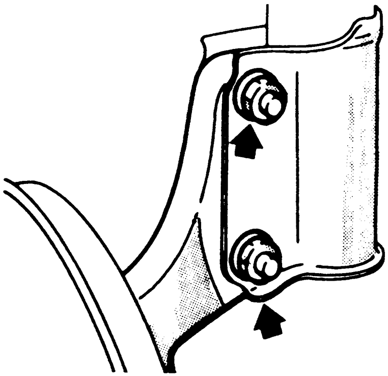
    Fig. 1: Removal of front strut lower mounting bolts

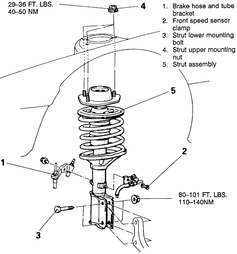
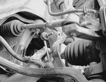
    Fig. 2: Front strut and related components

    To install:

  8. Install the strut to the vehicle and install the top mounting bolts. Make sure the insulator is installed so the matchmarks made during disassembly are in alignment. Tighten the mounting bolts to 36 ft. lbs. (50 Nm).
  9. Position the strut on the knuckle and install the mounting bolts. While holding the head of the lower mounting bolt, tighten the nuts to 80–101 ft. lbs. (110–140 Nm).

    Install the brake hose bracket and the ABS clamp.

  10. Install the wheel and tire assembly.
  11. Carefully lower the vehicle.
  12. Take the vehicle to a reputable repair shop to have the alignment checked and adjusted, if necessary.
1995–98 Vehicles

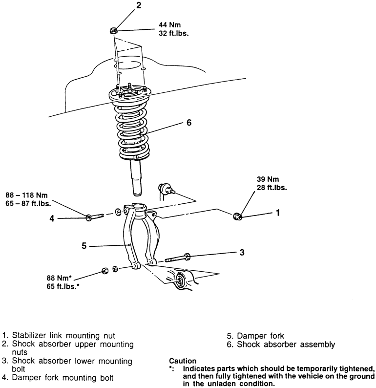
Fig. 3: Exploded view of the front strut assembly mounting

  1. Remove the top shock absorber assembly mounting nuts from inside the engine compartment.

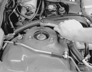
    Fig. 4: From inside the engine compartment, unfasten the upper shock assembly retaining bolts

  2. Raise and safely support the vehicle. Remove the wheel and tire assembly.
  3. Remove the stabilizer link mounting nut.

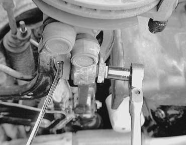
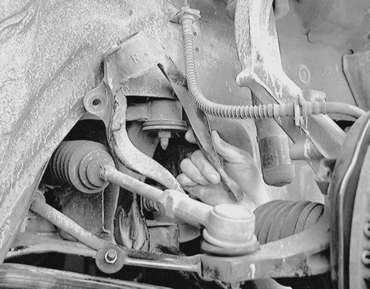
    Fig. 5: Unfasten the stabilizer link mounting nut . . .

    Fig. 6: . . . then separate the link from the damper fork

  4. Unfasten the shock absorber assembly lower mounting bolts.

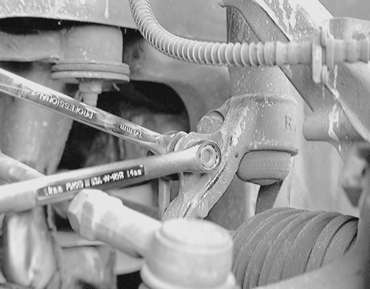
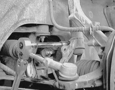
    Fig. 7: Use 2 wrenches to loosen the lower shock absorber retaining bolt . . .

    Fig. 8: . . . then remove the lower mounting bolt

  5. Remove the damper fork mounting bolt, then remove the damper fork from the vehicle.

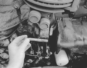
    Fig. 9: Use a ratchet and socket to loosen the damper fork retaining bolt . . .

    Fig. 10: . . . then remove the bolt and the damper fork assembly

  6. Remove the shock absorber assembly by maneuvering it out of the vehicle.

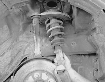
    Fig. 11: Maneuver the shock absorber assembly from the vehicle

  7. Installation is the reverse of the removal procedure. Be sure to tighten the retainers to the specifications shown in the accompanying figure.

Previous Next